Outer rotor radial magnetic bearing

An external rotor and magnetic bearing technology, applied in the field of non-contact magnetic suspension bearings, can solve the problems of permanent magnet bias radial magnetic bearing eddy current loss reduction, electromagnetic magnetic circuit coupling, and affecting the control accuracy of magnetic bearings, etc., to achieve eddy current loss reduction, The effect of improving the control precision

Active Publication Date: 2012-06-20
北京奇峰聚能科技有限公司
View PDF5 Cites 9 Cited by
  • Summary
  • Abstract
  • Description
  • Claims
  • Application Information

AI Technical Summary

Problems solved by technology

At present, in the field of hybrid radial magnetic suspension bearings, there are mainly electromagnetic magnetic circuit coupling problems in the radial x direction and y direction, which will affect the control accuracy of the magnetic bearing. Therefore, the existing radial magnetic bearings all have electromagnetic magnetic circuits in the radial direction. Defec

Method used


Image

  • Outer rotor radial magnetic bearing
  • Outer rotor radial magnetic bearing
  • Outer rotor radial magnetic bearing

Examples


Embodiment Construction

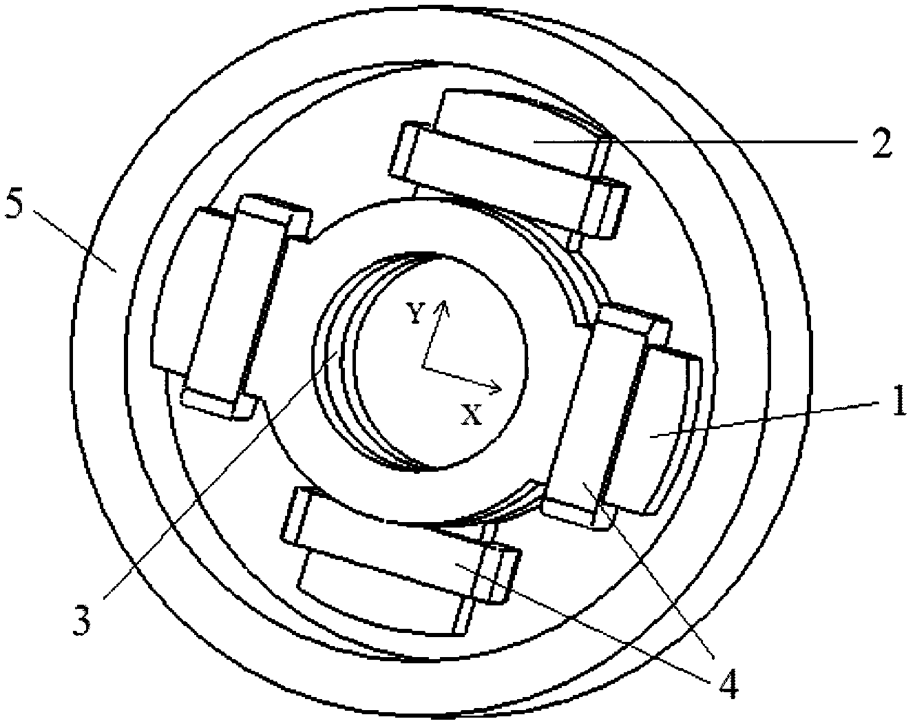
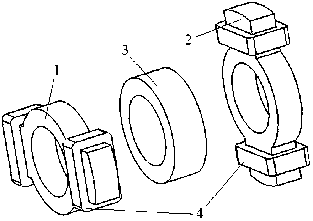
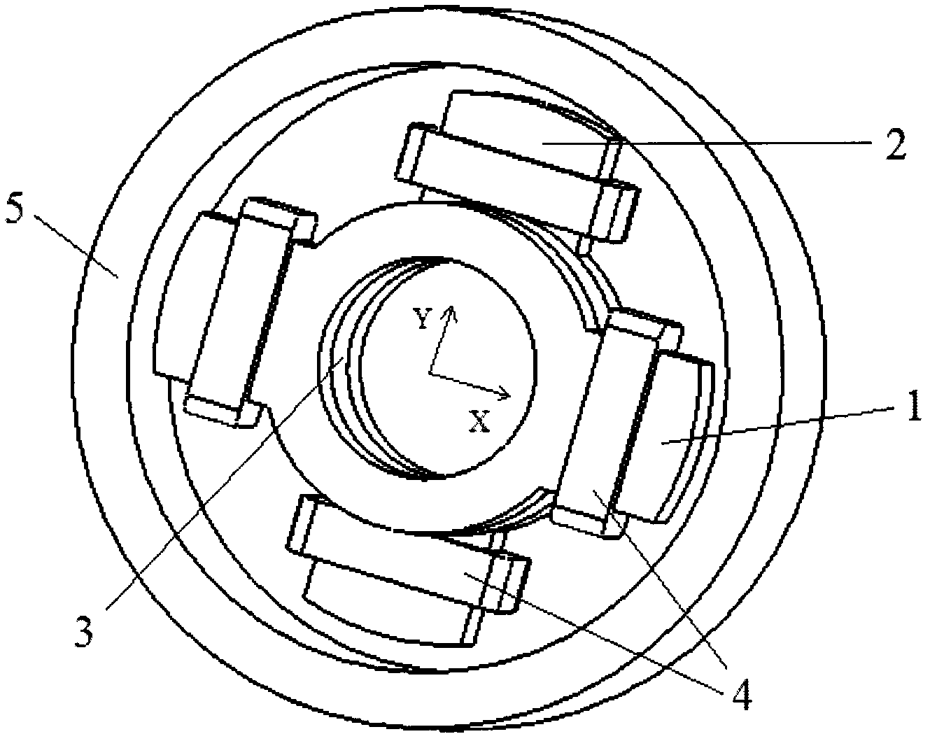
[0010] Such as figure 1 with figure 2 As shown, a radial magnetic bearing of the outer rotor of the present invention is composed of an inner stator core 1 in the x direction, an inner stator core 2 in the y direction, an inner permanent magnet 3, an inner coil 4 and an outer rotor core 5, wherein x The stator core 1 in the direction and the stator core 2 in the y direction are placed vertically, the stator core 1 in the x direction and the stator core 2 in the y direction each have two magnetic poles, and the inner coil 4 is wound on them, and the inner permanent magnet 3 is located at Between the inner stator core 1 in the x direction and the inner stator core 2 in the y direction, the radial outer part of the stator core 1 in the x direction and the inner stator core 2 in the y direction is the outer rotor core 5, and the inner stator core in the x direction A magnetic air gap is formed between the inner stator core 2 and the outer rotor core 5 in the 1 and y directions. ...


PUM


Abstract

The invention relates to an outer rotor radial magnetic bearing, which comprises a x direction inner stator iron core, a y direction inner stator iron core, an inner permanent magnet, inner coils and an outer rotor iron core, wherein the x direction inner stator iron core and the y direction inner stator iron core are placed vertically, the x direction inner stator iron core and the y direction inner stator iron core are respectively provided with two magnetic poles, the inner coils are wound on the magnetic poles, the inner permanent magnet is positioned between the x direction inner stator iron core and the y direction inner stator iron core, the radial outer parts of the x direction inner stator iron core and the y direction inner stator iron core are the outer rotor iron core, and themagnetic air gaps are formed between the x direction inner stator iron core, the y direction inner stator iron core and the outer rotor iron core. According to the present invention, the electromagnetic circuit is not subjected to coupling on the x direction and the y direction in the inner stator iron core of the radial magnetic bearing so as to improve the control precision of the radial magnetic bearing.

Description

technical field [0001] The invention relates to a non-contact magnetic suspension bearing, in particular to a permanent magnet bias magnetic bearing with radial decoupling of an outer rotor, which can be used as a non-contact support for rotor components in high-speed machinery. Background technique [0002] At present, magnetic suspension bearings are divided into pure electromagnetic bearings and hybrid magnetic suspension bearings with permanent magnetic bias and electromagnetic control. The former uses large current and power consumption, and hybrid magnetic suspension bearings with permanent magnetic bias and electromagnetic control. The electromagnetic field provides auxiliary adjustment. Bearing capacity, the magnetic field generated by the permanent magnet bears the main bearing capacity, so this kind of bearing can reduce the control current and reduce the loss. At present, in the field of hybrid radial magnetic suspension bearings, there are mainly electromagnetic ...

Claims


Application Information

Patent Timeline
IPC IPC(8): F16C32/04
Inventor 蒋涛
Owner 北京奇峰聚能科技有限公司
Why Eureka
Try Eureka