Driving device for pipe reducing device

A driving device and pipe shrinking technology, which is applied in the direction of transmission device, belt/chain/gear, mechanical equipment, etc., can solve the problems of liquid leakage, danger, inconvenient, etc., and achieve narrow pipe opening, strong mechanization, and reduce labor The effect of intensity

Inactive Publication Date: 2012-06-20
ZHEJIANG TENGYUN REFRIGENRATION TECH
View PDF5 Cites 0 Cited by
  • Summary
  • Abstract
  • Description
  • Claims
  • Application Information

AI Technical Summary

Problems solved by technology

[0002] Both the riser tube and the evaporator tube include an inner tube and an outer tube. During processing, the outer tube needs to be placed outside the inner tube, and the nozzle of the outer tube and the tube wall of the inner tube are welded together. Matching needs and other factors, the inner diameter of the outer tube needs to be larger than the outer diameter of the inner tube, resulting in a large gap between the inner and outer tubes, causing inconvenience in welding, if the welding is not good, it is easy to cause liquid leakage during use, cause danger; also cause unsightly appearance
[0003] We have specially developed a tube shrinking device, which can be seen in the patent application publication of the applicant with the patent application number of "CN201010600472.2" and the title of the invention "a tube shrinking device", but the rotation of this device is manual. Rotation is not convenient, the labor intensity of workers is high, and the degree of mechanization is not high

Method used


Image

  • Driving device for pipe reducing device
  • Driving device for pipe reducing device
  • Driving device for pipe reducing device

Examples


Embodiment

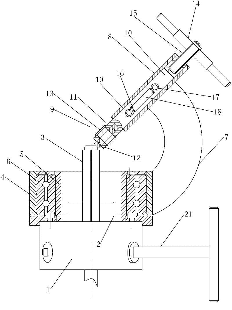
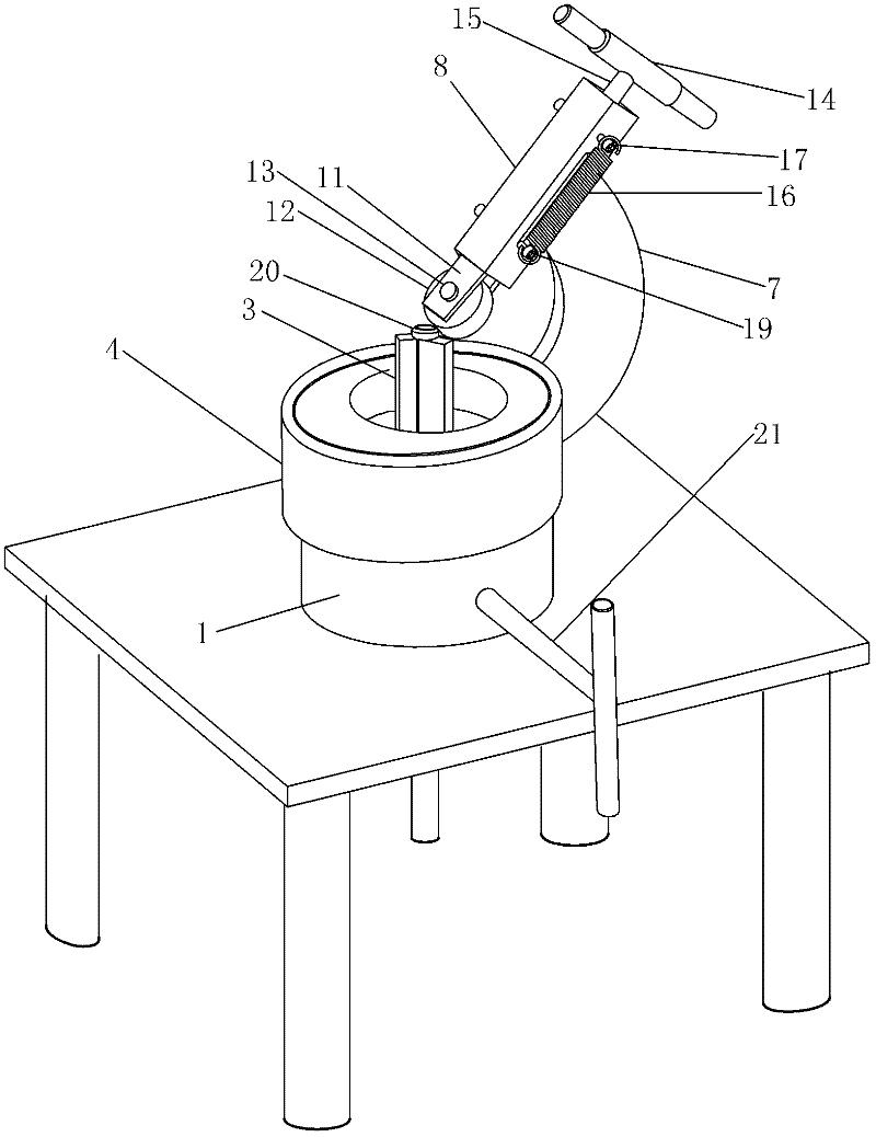
[0013] Example: such as Figure 1 ~ Figure 2 As shown, a semi-automatic tube shrinking device includes a clamping assembly for clamping the tube and a shrinking assembly for changing the size of the nozzle. The clamping assembly becomes a three-jaw chuck, and a three-jaw chuck It includes a fixed seat 1. Three claws 2 are provided on the fixed seat 1. Each claw 2 is provided with a clamping foot 3 that moves with the claw and clamps the pipe. The clamping foot 3 and the claw 2 are clamped The clamping foot 3 is 5 cm long.

[0014] The necking assembly includes two sleeves inside and outside. The outer sleeve 4 is sleeved outside the inner sleeve 5. The inner sleeve 5 is fixed on the fixed seat 1. A bearing 6 is arranged between the inner and outer sleeves. The inner ring and the outer ring of 6 are respectively connected to the inner sleeve 5 and the outer sleeve 4. The outer sleeve 4 rotates around the longitudinal central axis 9 of the fixing seat 1 of the clamping assembly, a...


PUM

PropertyMeasurementUnit
Lengthaaaaaaaaaa

Abstract

The invention discloses a driving device for a pipe reducing device, which comprises a motor, a first transmission mechanism and a second transmission mechanism. The first transmission mechanism comprises a large belt pulley and a first reduction gear which are coaxially mounted, the second transmission mechanism comprises a second large reduction gear and a second small reduction gear which are coaxially mounted, the large belt pulley is in transmission connection with a small belt pulley mounted on an output shaft of the motor, the second large reduction gear is engaged with the first reduction gear, a large gear is fixedly sleeved outside an outer sleeve of the pipe reducing device, and the second small reduction gear is engaged with the large gear. The driving device adopts the motor for driving, the outer sleeve rotates along the longitudinal central axis of a clamping assembly fixing seat, and rollers continuously rotate to press a pipe orifice inwards, so that the pipe orifice can be uniformly reduced. Besides, the degree of mechanization is higher, and the labor intensity of workers is reduced.

Description

Technical field [0001] The invention relates to the field of nozzle processing, in particular to a driving device for a tube shrinking device. Background technique [0002] Both the riser and the evaporator tube include an inner tube and an outer tube. During processing, the outer tube needs to be sleeved outside the inner tube, and the nozzle of the outer tube and the wall of the inner tube must be welded together. There are many factors such as the need for matching. The inner diameter of the outer tube needs to be larger than the outer diameter of the inner tube, resulting in a large gap between the inner and outer tubes, causing inconvenience in welding. If the welding is not good, it is easy to cause liquid leakage during use. Cause danger; and cause unsightly appearance. [0003] Specially developed a tube shrinking device. Specifically, it can be seen that the applicant’s invention patent application number is: "CN201010600472.2", and the invention name is "A tube shrinking...

Claims


Application Information

Patent Timeline
IPC IPC(8): F16H37/02B21D41/04
Inventor 沈小毛蔡忠海杨永金沈松月
Owner ZHEJIANG TENGYUN REFRIGENRATION TECH
Why Eureka
Try Eureka