Semiautomatic pipe reducing device

A semi-automatic, driving device technology, applied in the field of nozzle processing, can solve problems such as danger, liquid leakage, welding inconvenience, etc., and achieve the effects of reducing labor intensity, reducing nozzle size, and increasing the degree of mechanization

Inactive Publication Date: 2012-01-18
ZHEJIANG TENGYUN REFRIGENRATION TECH
View PDF7 Cites 0 Cited by
  • Summary
  • Abstract
  • Description
  • Claims
  • Application Information

AI Technical Summary

Problems solved by technology

[0002] Both the riser tube and the evaporator tube include an inner tube and an outer tube. During processing, the outer tube needs to be placed outside the inner tube, and the nozzle of the outer tube and the tube wall of the inner tube are welded together. Matching needs and other factors, the inner diameter of the outer tube needs to be larger than the outer diameter of the inner tube, resulting in a large gap between the inner and outer tubes, causing inconvenience in welding, if the welding is not good, it is easy to cause liquid leakage during use, cause danger; also cause unsightly appearance

Method used


Image

  • Semiautomatic pipe reducing device
  • Semiautomatic pipe reducing device
  • Semiautomatic pipe reducing device

Examples


Embodiment

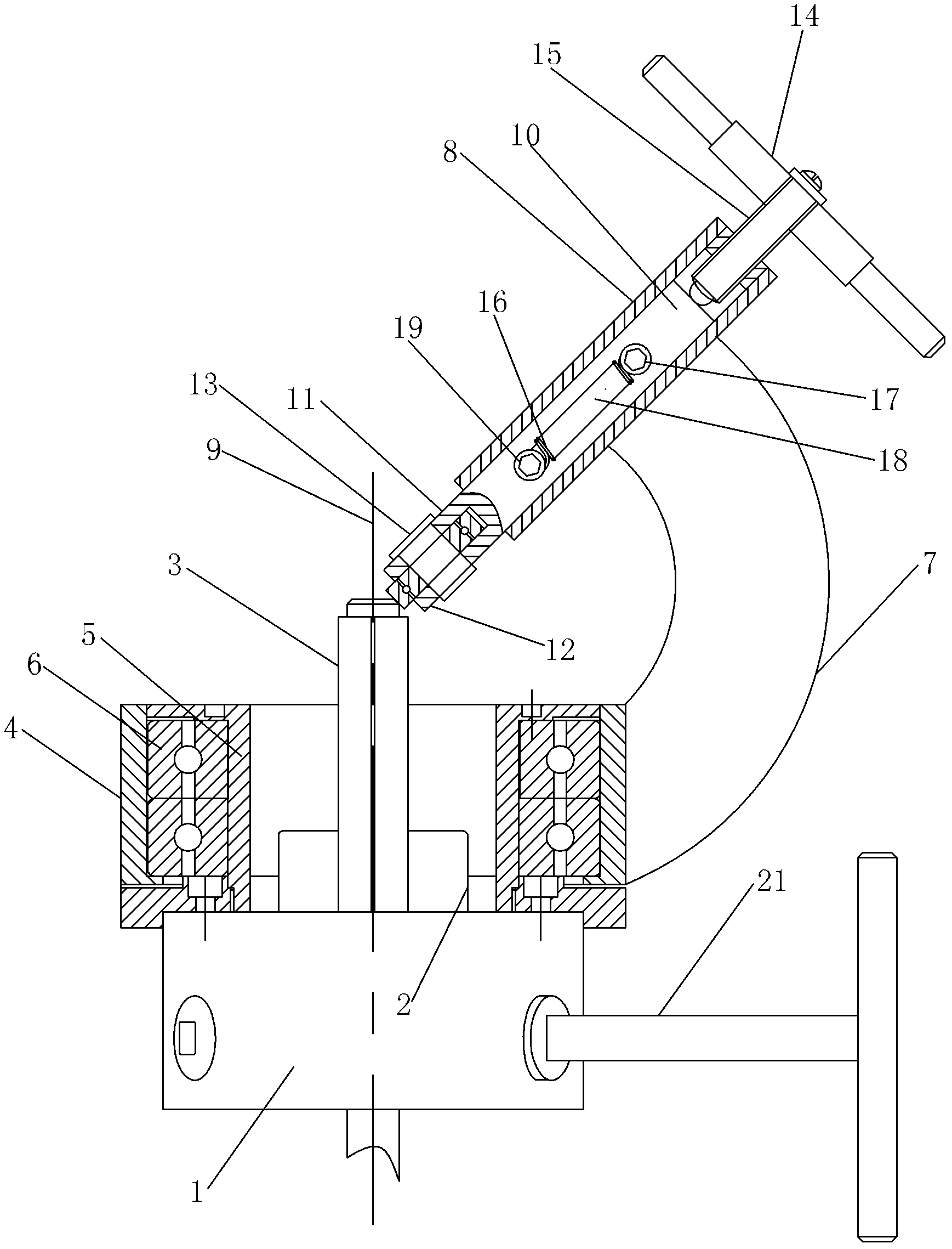
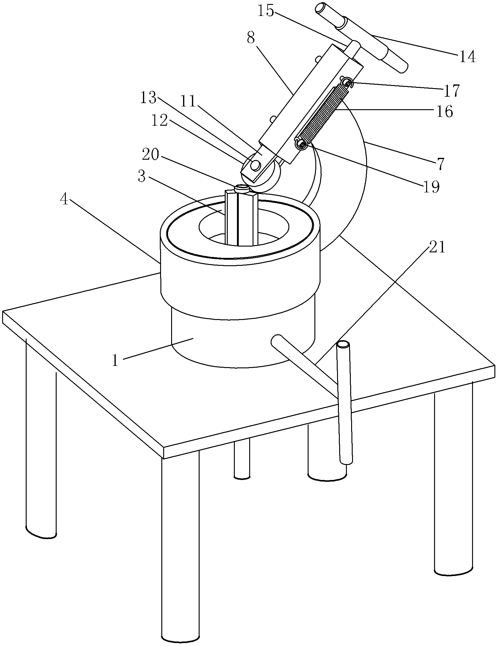
[0019] Example: such as Figure 1 ~ Figure 2 As shown, a semi-automatic shrinking device includes a clamping assembly for clamping the pipe and a shrinking assembly for changing the size of the nozzle. The clamping assembly is a three-jaw chuck, and the three-jaw chuck It includes a fixed base 1, on which there are three claw bodies 2, and each claw body 2 is provided with a clamping foot 3 that moves with the claw body and clamps the pipe, and the clamping foot 3 and the claw body 2 adopt a clamp Connecting way, thereby can convenient loading and unloading, the length of described clamping foot 3 is 5cm.

[0020] The necking assembly includes two inner and outer sleeves, the outer sleeve 4 is set outside the inner sleeve 5, the inner sleeve 5 is fixed on the fixed seat 1, and a bearing 6 is arranged between the inner and outer sleeves. The inner ring and the outer ring of 6 are respectively connected with the inner sleeve 5 and the outer sleeve 4, and the outer sleeve 4 rota...


PUM

PropertyMeasurementUnit
lengthaaaaaaaaaa
lengthaaaaaaaaaa

Abstract

The invention discloses a semiautomatic pipe reducing device, which comprises a clamping assembly for clamping a pipe and a necking assembly for changing the size of a pipe orifice; the necking assembly rotates around the longitudinal central shaft of the clamping assembly; the necking assembly comprises a guide sleeve obliquely arranged relative to the horizontal plane; a telescopic roller seat is arranged in the guide sleeve; a roller for pressing the pipe orifice is arranged at the lower end of the roller seat; the roller is obliquely arranged relative to the horizontal plane; a handle for driving the roller seat to move is arranged at the upper end of the roller seat; and the necking assembly is connected with a driving device for driving the necking assembly to rotate around the clamping assembly. Through the driving device, the roller rotates to continually inwards press the pipe orifice, so that the pipe orifice can be uniformly reduced, the mechanical degree is stronger, and the labor intensity of a worker is lightened.

Description

technical field [0001] The invention relates to the field of nozzle processing, in particular to a device for reducing the diameter of the nozzle. Background technique [0002] Both the riser tube and the evaporator tube include an inner tube and an outer tube. During processing, the outer tube needs to be placed outside the inner tube, and the nozzle of the outer tube and the tube wall of the inner tube are welded together. Matching needs and other factors, the inner diameter of the outer tube needs to be larger than the outer diameter of the inner tube, resulting in a large gap between the inner and outer tubes, causing inconvenience in welding, if the welding is not good, it is easy to cause liquid leakage during use, cause danger; and cause unsightly appearance. Contents of the invention [0003] Aiming at the deficiencies in the above-mentioned prior art, the present invention provides a semi-automatic tube shrinking device which is reasonable in structure, easy to u...

Claims


Application Information

Patent Timeline
Patent Type & Authority Applications(China)
IPC IPC(8): B21D41/04
Inventor 沈小毛蔡忠海杨永金沈松月
Owner ZHEJIANG TENGYUN REFRIGENRATION TECH
Why Eureka
Try Eureka