Backlight mould and manufacturing method thereof

A technology of a backlight module and a manufacturing method, which is applied in the field of backlight modules and its manufacture, can solve the problems that the backlight and the light guide plate cannot be tightly combined, affect the brightness and optical quality of the backlight, and achieve the improvement of the brightness and optical quality of the backlight, assembly easy effect

Inactive Publication Date: 2012-06-20
AU OPTRONICS CORP
View PDF0 Cites 6 Cited by
  • Summary
  • Abstract
  • Description
  • Claims
  • Application Information

AI Technical Summary

Problems solved by technology

[0004] Aiming at the defects in the prior art that the double-sided adhesive can affect the brightness and optical quality of the backlight, and

Method used


Image

  • Backlight mould and manufacturing method thereof
  • Backlight mould and manufacturing method thereof
  • Backlight mould and manufacturing method thereof

Examples


Embodiment Construction

[0020] The specific implementation manners of the present invention will be described in further detail below with reference to the accompanying drawings.

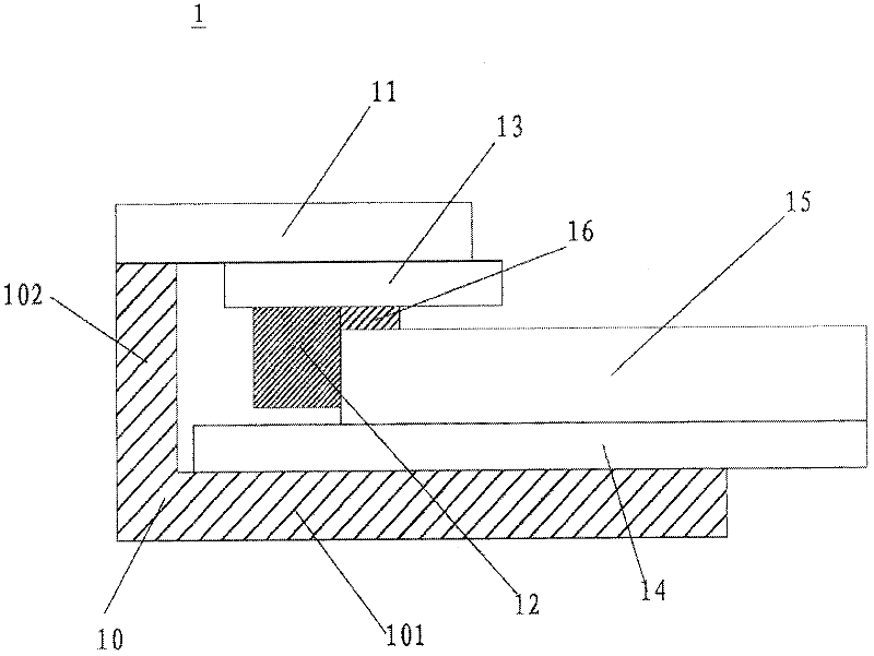
[0021] figure 1 A schematic cross-sectional view of a backlight module in the prior art is shown. refer to figure 1 , The backlight module 1 includes: an outer frame 10 , a plastic frame 11 , a backlight source 12 , a circuit board 13 , a reflector 14 and a light guide plate 15 . The outer frame 10 has a first side wall 101 and a second side wall 102 , the plastic frame 11 is erected on the second side wall 102 of the outer frame 10 and is formed with the first side wall 101 and the second side wall 102 of the outer frame 10 Storage space with side opening. The reflector 14 is located on the second side wall 102 of the outer frame 10, the circuit board 13 is located below the plastic frame 11, the backlight 12 is located below the circuit board 13, the light guide plate 15 is located on the reflector 14, and is located ...


PUM


Abstract

The invention provides a backlight mould which comprises an outer frame, a reflector, a circuit board, a backlight source and a light guide plate, wherein the outer frame is provided with a containing space one side of which is provided with an opening, the reflector is arranged in the containing space of the outer frame, and the upper and lower walls of the reflector are respectively fitted on the upper and lower walls of the outer frame; the circuit board is pasted on the lower surface of the upper wall of the reflector, and the backlight source is fixed on the lower surface of the circuit board and is fitted with the lower wall of the reflector; and the light guide plate is fitted on the backlight source and clamped between the circuit board and the lower wall of the reflector. The invention also provides a manufacturing method of the backlight mould; the manufacturing method comprises the following steps: providing the circuit board with the backlight source, pasting the circuit board on the reflector, overturning the circuit board pasting the reflector, and forming buckling; providing the outer frame, providing the containing space one side of which is provided with the opening, pushing the reflector in the containing space of the outer frame; providing the light guide plate to push the reflector to the interior of the outer frame; and adopting the backlight source and the light guide plate which can be closely connected, and promoting backlight brightness and optical quality.

Description

technical field [0001] The invention relates to a backlight module and a manufacturing method thereof, in particular to a backlight module capable of improving brightness. Background technique [0002] At present, various types of liquid crystal displays mainly adopt a combined structure of a panel and a backlight module. The backlight module mainly provides a surface light source with uniform brightness, and the panel modulates the optics to realize the display function. The current backlight module will fix the light guide plate through the bending design of the outer frame, and place the backlight in the bending part of the outer frame. The circuit board is made into a reverse group structure, so that the backlight circuit board is pasted on the top of the light guide plate. However, under the reverse group structure, it is not easy to paste the backlight in the bend of the outer frame, so the reverse group structure assembly is mostly The plastic frame and the backlight...

Claims


Application Information

Patent Timeline
IPC IPC(8): F21S8/00F21V17/10
Inventor 简元禹
Owner AU OPTRONICS CORP
Why Eureka
Try Eureka