
Expansion valve

An expansion valve and spool technology, applied in the field of expansion valves, can solve the problems of difficult welding process, complex mechanism, slow response time, etc., and achieve the effect of facilitating accurate flow control, realizing forward and reverse flow control, and system reliability

Active Publication Date: 2014-05-07
ZHEJIANG DUNAN ARTIFICIAL ENVIRONMENT
View PDF6 Cites 0 Cited by
  • Summary
  • Abstract
  • Description
  • Claims
  • Application Information

AI Technical Summary

Problems solved by technology

Among them, the thermal expansion valve controls the refrigerant flow into the evaporator by sensing the superheat of the refrigerant at the outlet of the evaporator. The reaction time is slow, the welding process is difficult, and the precise control of the refrigerant cannot be realized; the electronic expansion valve controls the valve through a stepping motor. The opening of the opening can accurately control the refrigerant flow, but the flow control cannot be completely linear, and the mechanism is complicated, and the system reliability is not good

Method used


Image

  • Expansion valve
  • Expansion valve
  • Expansion valve

Examples


Embodiment Construction

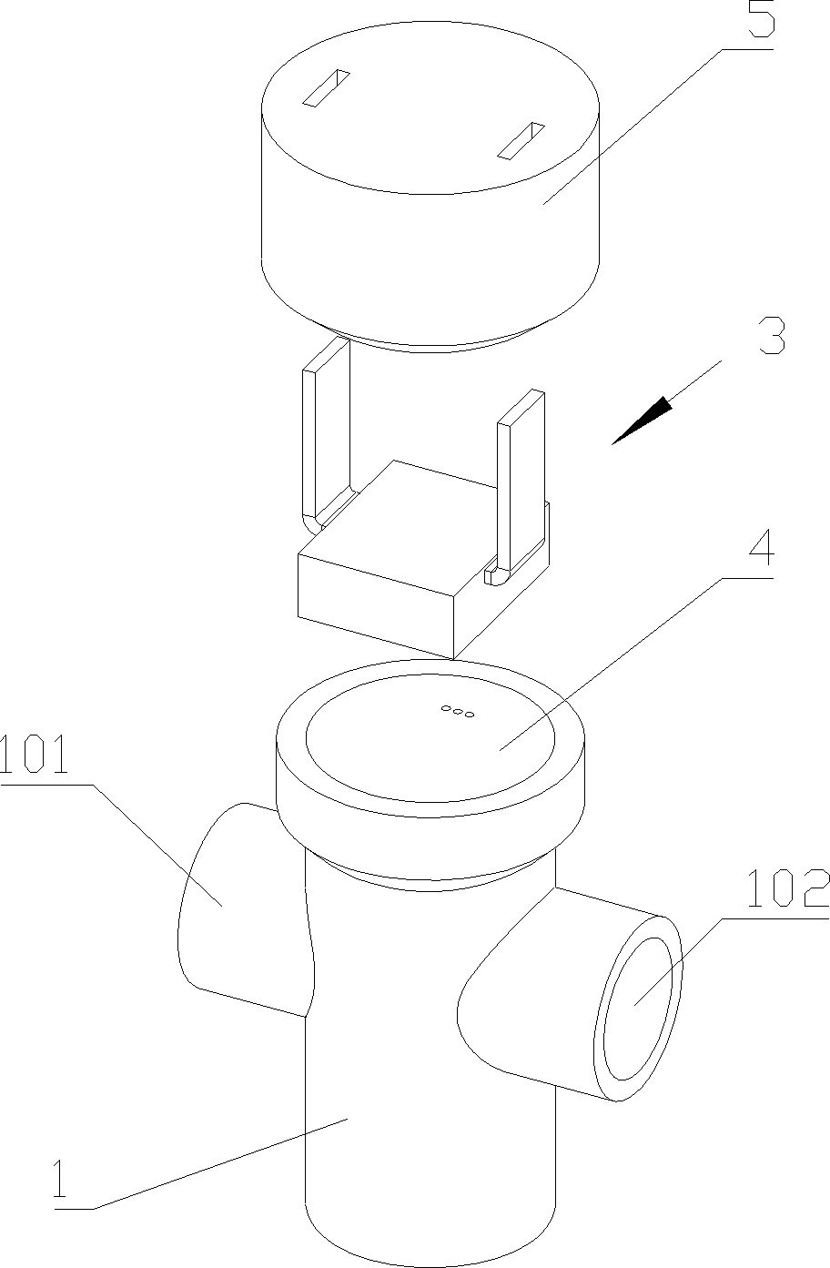
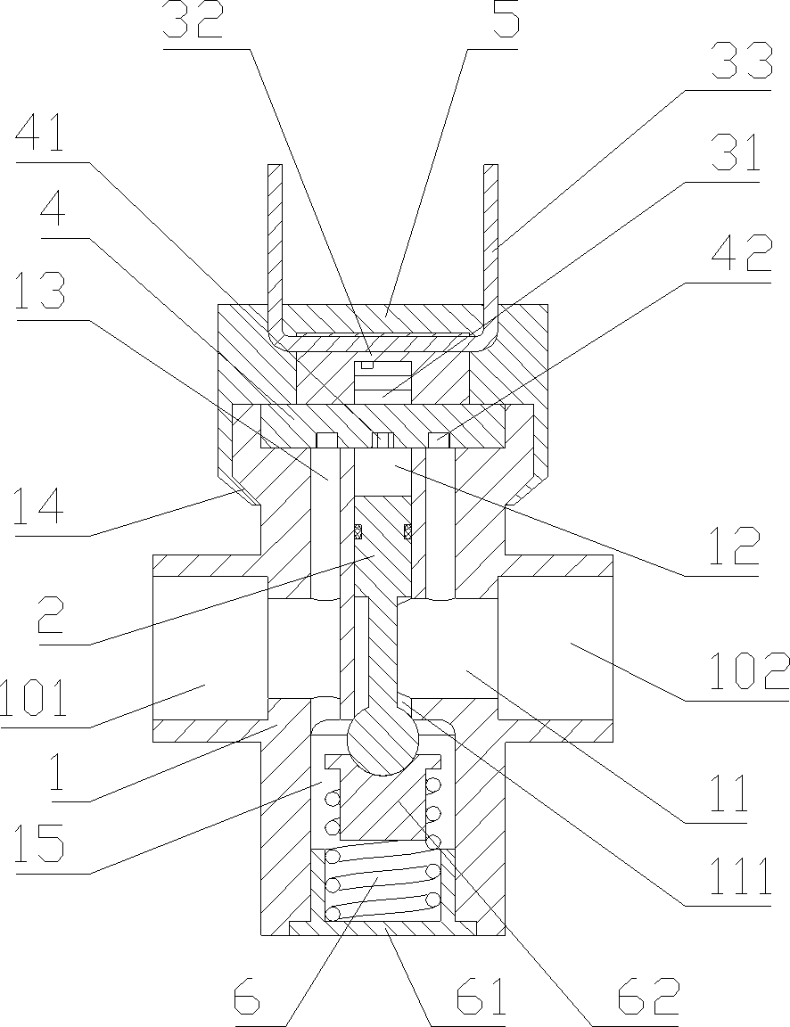
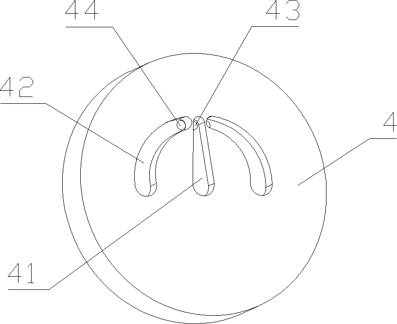
[0021] Such as Figure 1 to 5 Shown is a schematic structural view of an embodiment of the present invention. An expansion valve includes a valve body 1, a valve core 2 and a drive component 3. The valve body is transversely provided with a first flow passage 11 for refrigerant to circulate, and the first flow passage communicates with The inlet 101 and outlet 102 of the valve body are vertically provided with a main flow hole 12 above the first flow passage in the valve body, and a main flow port 111 is provided in the first flow passage corresponding to the main flow hole. The upper part of the valve core is set in the main flow hole to remove the main flow The hole is disconnected from the first flow channel, and the lower part of the valve core corresponds to the main flow port. The valve core moves up and down along the main flow hole to open or close the main flow port. A second flow parallel to the main flow hole is also provided in the valve body above the first flow cha...


PUM


Abstract

The invention discloses an expansion valve, which comprises a valve body, a spool and a driving part. A first flow passage for refrigerant to flow is transversely arranged in the valve body. The first flow passage is communicated with the inlet and the outlet of the valve body. A main flow hole is vertically arranged in the valve body above the first flow passage. A main flow port is arranged in the first flow passage at a position corresponding to the main flow hole. The upper part of the spool is arranged in the main flow hole to isolate the main flow hole from the first flow passage. The lower part of the spool corresponds to the main flow port. The spool moves up and down along the main flow hole to open or close the main flow port. A second flow passage which is in parallel with the main flow hole is additionally arranged in the valve body at a position above the first flow passage. The second flow passage is communicated with the first flow passage. A diversion structure is arranged between the second flow passage and the main flow hole. A silicon wafer for opening or closing the diversion structure is arranged in the driving part. The expansion valve has the advantages that the structure is simple, the expansion valve is convenient to manufacture, the flow of the refrigerant can be accurately controlled, the power consumption is low and the safety and the reliability are high.

Description

Technical field [0001] The present invention relates to a valve, especially an expansion valve. Background technique [0002] In existing air conditioning systems, thermal expansion valves and electronic expansion valves have been mostly used. The thermal expansion valve controls the refrigerant flow into the evaporator by sensing the superheat of the refrigerant at the outlet of the evaporator. The reaction time is slow, the welding process is difficult, and the precise control of the refrigerant cannot be achieved; the electronic expansion valve is controlled by a stepping motor. The opening degree of the port can accurately control the refrigerant flow, but the flow control cannot be completely linear, and the mechanism is complicated and the system reliability is not good. Summary of the invention [0003] The problem to be solved by the present invention is to provide an expansion valve with simple structure, convenient processing, accurate control of refrigerant flow, low p...

Claims


Application Information

Patent Timeline
Patent Type & Authority Patents(China)
IPC IPC(8): F25B41/06
Inventor 康志军张胜昌王鑫楠俞玲霞
Owner ZHEJIANG DUNAN ARTIFICIAL ENVIRONMENT
Learn More