
Method for measuring concrete vibrating time in real-time

A real-time detection and concrete technology, applied in measuring devices, material analysis by electromagnetic means, instruments, etc., can solve problems such as the inability to objectively and accurately control/evaluate the quality of concrete pouring, and achieve the effect of facilitating construction

Active Publication Date: 2013-09-25
HOHAI UNIV
View PDF4 Cites 0 Cited by
  • Summary
  • Abstract
  • Description
  • Claims
  • Application Information

AI Technical Summary

Problems solved by technology

[0003] Obviously, the traditional method of relying on experience cannot timely, accurately and completely know the vibration behavior of concrete pouring, so it cannot objectively and accurately control / evaluate the quality of concrete pouring

Method used


Image

  • Method for measuring concrete vibrating time in real-time
  • Method for measuring concrete vibrating time in real-time
  • Method for measuring concrete vibrating time in real-time

Examples


Embodiment Construction

[0020] The accompanying drawings disclose, without limitation, the structural schematic diagrams of the preferred embodiments involved in the present invention; the technical solution of the present invention will be described in detail below in conjunction with the accompanying drawings.

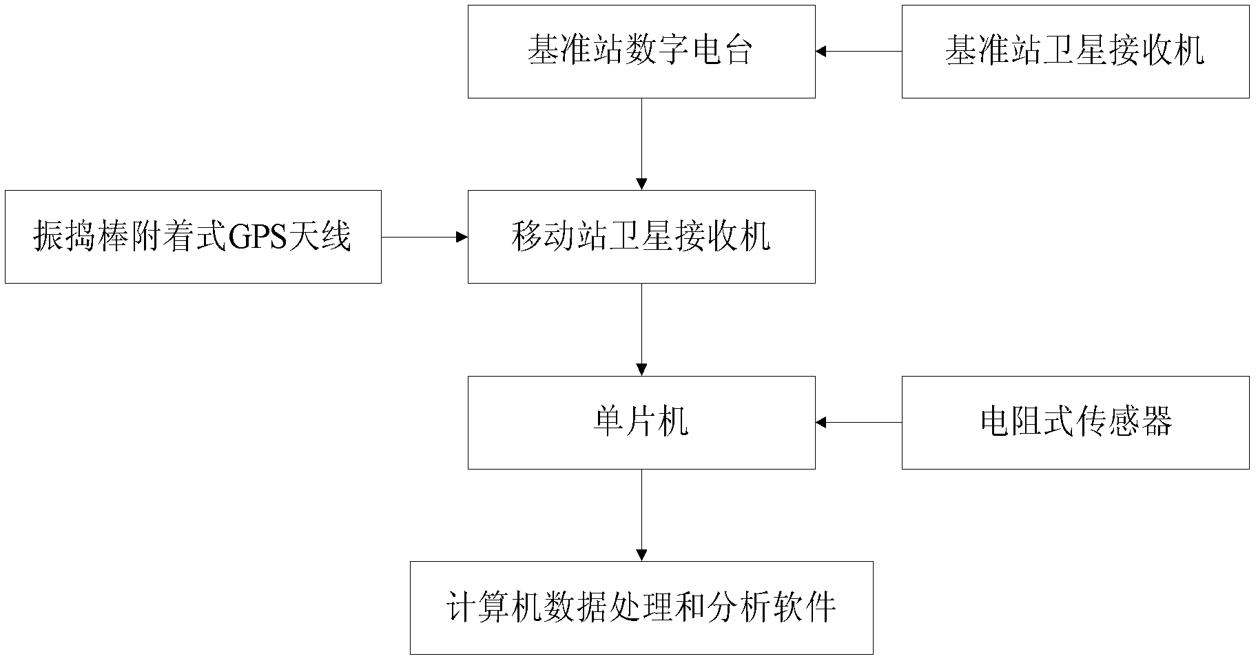
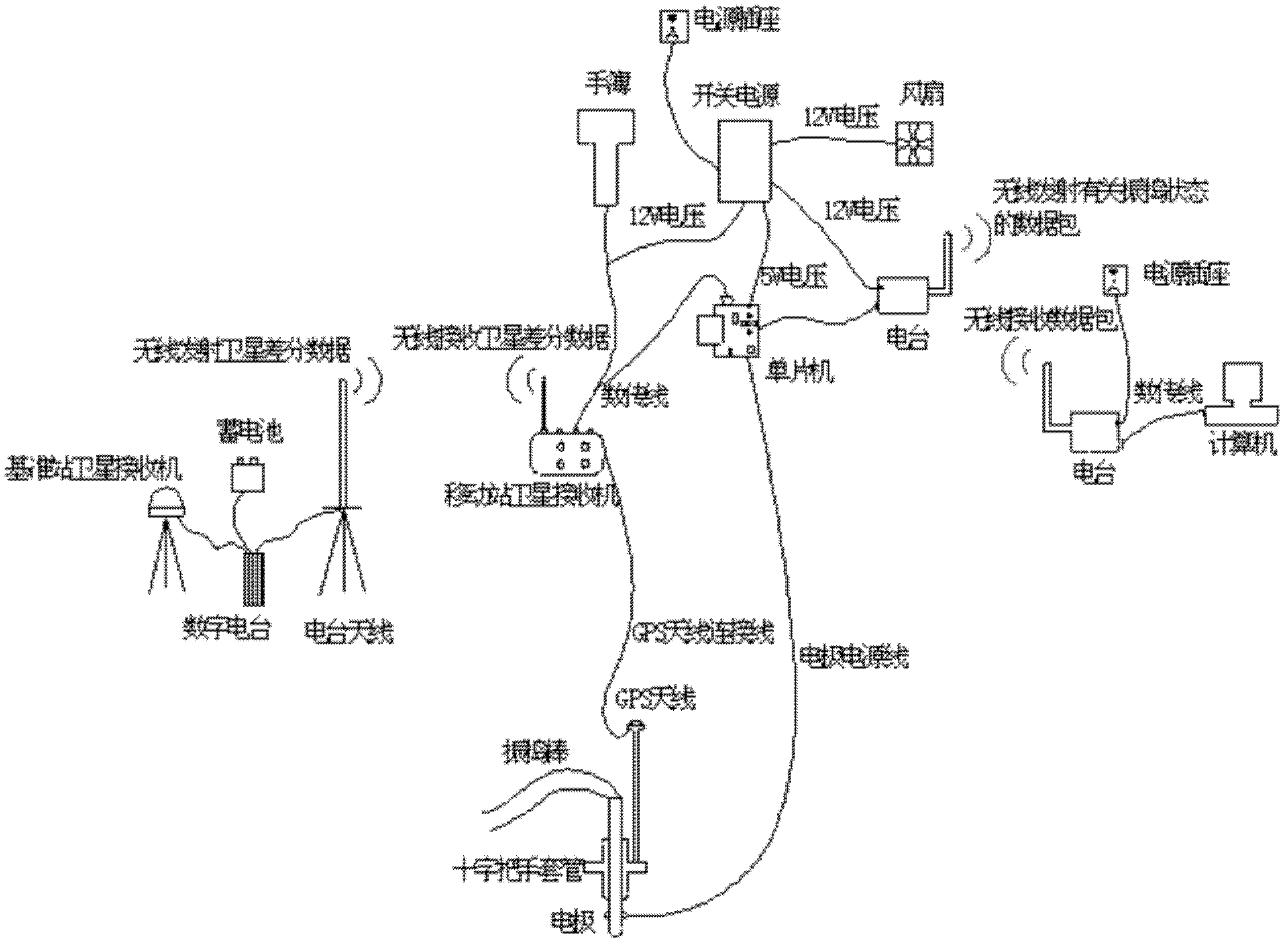
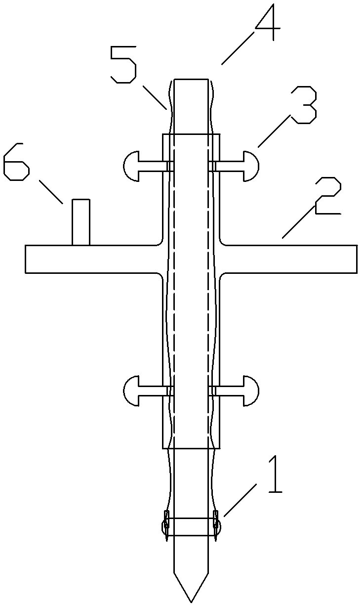
[0021] Such as Figures 1 to 4 As shown, a complete concrete vibrating dynamic visual monitoring method mainly includes the following parts: real-time feedback of vibrating state, real-time feedback of vibrating time, visual display after integrating vibrating state and vibrating time, Specifically, it includes the following steps: 1) Determination of the vibration track and vibration time of the vibrating rod—firstly, an electrode for measuring the potential of the concrete mixture to be measured is installed on one end of the vibrating rod, and the other end is Install the GPS antenna; secondly, plug the vibrating rod into and out of the concrete mixture to be tested, and when the vibrati...


PUM


Abstract

The invention discloses a method for measuring concrete vibrating time in real-time, which comprises the following steps: firstly, an electrode used for measuring electric potential of to-be-measured concrete is mounted at a head of a spud vibrator; and then, the electrode is connected with a single chip through a power cord; the single chip collects and analyzes electric potential values fed back by the electrode when the spud vibrator is inserted in and pulled out of the to-be-measured concrete, and calculates the vibrating time t of the spud vibrator, so as to feed back the vibrating time for the spud vibrator to be inserted in and pulled out of the to-be-measured concrete in real-time. Therefore, the method utilizes the differences existing in the electric potential values when the spud vibrator is inserted in and pulled out the concrete, so as to monitor the time interval that the spud vibrator is inserted in and pulled out of the concrete, i.e. the vibrating time, and relatively accurately calculate the vibrating time of the spud vibrator in the to-be-measured concrete, and provide indispensable important technical parameters for acquiring the pouring and the vibrating states of the concrete in real-time in an visualized manner.

Description

technical field [0001] The invention relates to a detection method for the vibration time of a vibrating rod in concrete, belonging to the field of concrete pouring quality control. Background technique [0002] Reliable testing and overall evaluation of the vibrating effect of fresh concrete pouring is one of the important links in concrete quality control. At present, the vibrating method used on the construction site is to consider the radius of action of the vibrating rods, and it is required to insert the vibrating rods in a staggered manner to ensure that the concrete pouring area is basically vibrated and compacted. The vibrating time of the vibrating rod / vibrating spacing and the vibrating method need to be determined by the field operator based on experience based on factors such as the workability of the fresh concrete into the warehouse / geometry of the pouring part / formwork conditions / pouring thickness / reinforcement density. Judging whether the concrete is compac...

Claims


Application Information

Patent Timeline
Patent Type & Authority Patents(China)
IPC IPC(8): G01N27/00G01N27/06
Inventor 田正宏毛龙边策邓会江
Owner HOHAI UNIV
Learn More