Wideband beam forming method based on error constraints of directions of arrival and forming device

An error-constrained, beamforming technology, applied to instruments, radio wave measurement systems, space transmit diversity, etc., can solve problems such as not fully utilizing the beamformer

Active Publication Date: 2012-06-20
TSINGHUA UNIV
View PDF3 Cites 7 Cited by
  • Summary
  • Abstract
  • Description
  • Claims
  • Application Information

AI Technical Summary

Problems solved by technology

The algorithm is robust, but it does not make full use of the degrees of freedom of the beamformer, so there is room for improvement in its synthesis performance

Method used


Image

  • Wideband beam forming method based on error constraints of directions of arrival and forming device
  • Wideband beam forming method based on error constraints of directions of arrival and forming device
  • Wideband beam forming method based on error constraints of directions of arrival and forming device

Examples


preparation example Construction

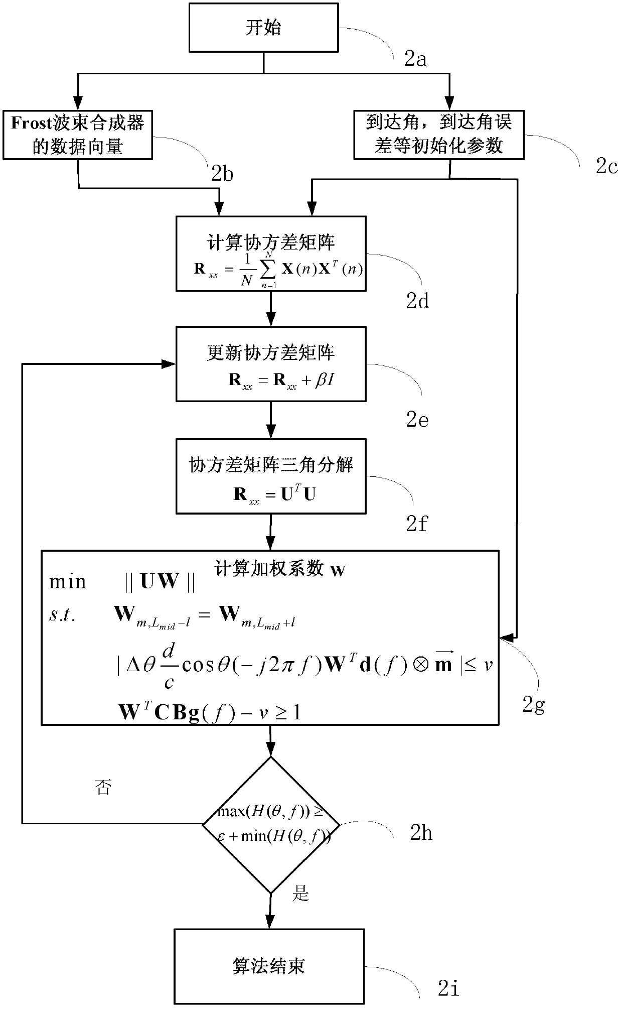
[0143] The wideband beamforming method proposed by the present invention based on the angle-of-arrival error constraint, such as figure 2 shown, perform the following steps in sequence:

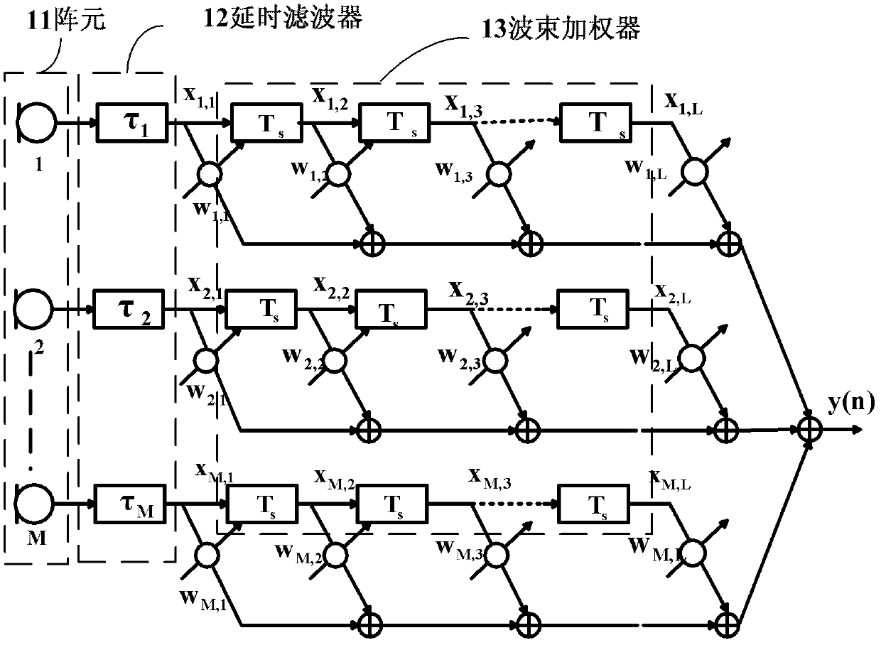
[0144] After the positioning calculation starts, the computer simultaneously transfers from step 2a to steps 2b and 2c which are executed in parallel. Wherein step 2b is based on the data vector x of the front-end Frost beamformer l (n) (l=2, . . . , L) resultant vector X(n), where L is the order of the weighter.

[0145] X T ( n ) = [ x 1 T ( n ) , x 2 T ( n ) , . . . , x L T ( ...

Embodiment 1

[0176] Embodiment 1: This embodiment uses software to implement the positioning method proposed by the present invention, such as figure 2 shown. The positions of each array element are located at [0 0 0], [0.015 0 0], [0.030 0 0], [0.045 0 0], [0.060 0 0], [0.075 0 0], [0.090 0 0], [0.105 0 0], [0.120 0 0], [0.135 0 0]. Signal arrival direction θ=40°, interference direction θ 1 =-20°. Signal azimuth error Δθ=4°. The input signal is a linear frequency modulation signal, and the signal carrier frequency is f 0 =12G, bandwidth B=2G. After beamforming starts, step 2a is simultaneously transferred to steps 2b and 2c which are executed in parallel. Wherein step 2b is based on the data vector x of the front-end Frost beamformer l (n) synthetic vector X(n)

[0177] X(1)=[-55.6, -59.5, 109, 56.6, 51.2, 8.2, -14.8, 23.4, ...] T

[0178] Step 2c is to initialize the beamformer data, including angle of arrival θ=40°, angle of arrival error Δθ=4°,

[0179]

[0180] ...

Embodiment 2

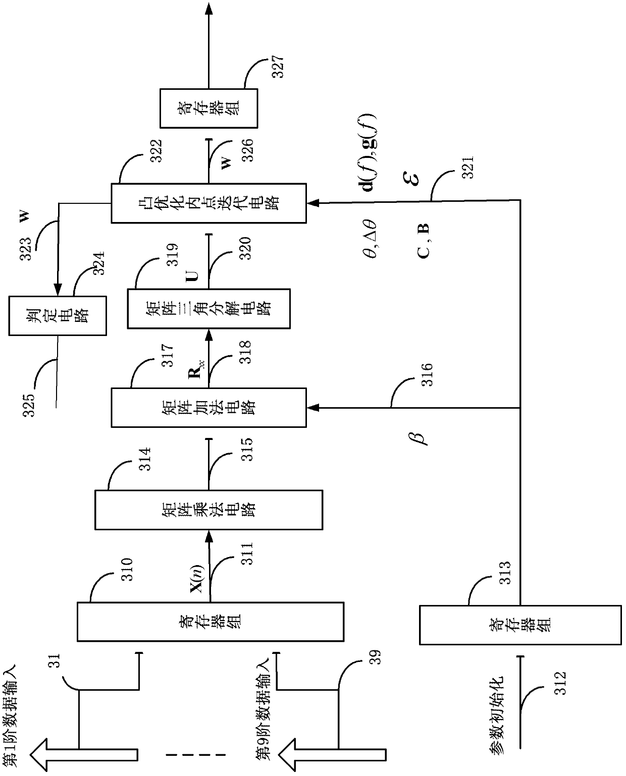
[0185] Embodiment 2: This embodiment uses hardware to implement the beamforming method proposed in the present invention. Still take the example that the number of array elements M=10 and the order of the weighter is L=9. The positioning process of the hardware circuit, such as image 3 As shown, the first to ninth order data circuits 31-39 provided by the front-end Frost are stored in a register bank 310, thereby providing a data vector 311 (X(n)) for subsequent processing; initialization parameter circuit 312, and put The parameters are stored in the register group 313; the data vector X (n) passes through the matrix multiplication circuit 314, and the matrix multiplication circuit transposes the vector and multiplies it with the original vector to obtain the matrix 315; then the matrix and the initialized parameter (βI) are added through the matrix Circuit 317, obtain data matrix 318 (R xx ); to matrix 318 through matrix triangular decomposition circuit 319, obtain upper ...


PUM


Abstract

The invention discloses a wideband beam forming method based on error constraints of directions of arrival and a forming device. The wideband beam forming method is characterized by comprising a step 1: adding a unit matrix with a covariance matrix after the unit matrix is multiplied by coefficient beta, and obtaining an updated covariance matrix; and a step 2, calculating W according to formula:min WTRxxW+beta WTW, wherein W meets the condition of WTCBg(f)-v> / =1. By the aid of the wideband beam forming method and the forming device, signals can pass to the greatest extent within an error range of the directions of arrival (DOA), and simultaneously, certain ripples of response of the signals are realized.

Description

technical field [0001] The invention relates to the field of array signal processing, in particular to a broadband beam synthesis method and a synthesizer based on an angle-of-arrival error constraint. Background technique [0002] There is a frequency-dependent phase difference between the broadband signals received by the array elements, so when conventional complex weighting is directly applied to broadband beam synthesis, the synthesis performance cannot be optimal. Broadband beamforming is based on the Frost beamformer. In practical applications, due to the influence of array amplitude and phase inconsistency, array element position error, mutual coupling and arrival angle error, the beamforming performance is greatly affected, so the robustness is Key factors in wideband beamforming. [0003] Robust wideband beamforming plays an important role in realizing spatial filtering of signals, thereby improving the quality of desired signals. Robust broadband beamforming can...

Claims


Application Information

Patent Timeline
IPC IPC(8): G01S7/52G01S7/02H04B7/08
Inventor 黄振陆建华陈云
Owner TSINGHUA UNIV
Why Eureka
Try Eureka