Remnant object detection method and device

A detection method and a technique for remnants, which are applied in the field of video surveillance to achieve the effects of eliminating false detections, improving detection accuracy, and reducing false detection rates

Active Publication Date: 2012-06-20
CRSC COMM & INFORMATION GRP CO LTD
View PDF3 Cites 35 Cited by
  • Summary
  • Abstract
  • Description
  • Claims
  • Application Information

AI Technical Summary

Benefits of technology

In this technology described in previous examples, it suggests comparing two images based on their own characteristics such as color or gray levels. By doing things like removing any unwanted parts of an object's appearance when looking at them later compared with those already existing ones, we aimed towards reducing errors associated with identifiable patterns found within these scenes. Overall, our approach provides improved systems capable of accurately distinguishing real world elements without being affected by external factors like light conditions.

Problems solved by technology

The technical problem addressed in this patented solution involves improving the reliability and efficiency of identifying objects (retrocars) within videos captured from different angles during daylight hours without causing issues like shadows changing overnight caused by light fluctuations at nightfall.

Method used


Image

  • Remnant object detection method and device
  • Remnant object detection method and device
  • Remnant object detection method and device

Examples


Embodiment 1

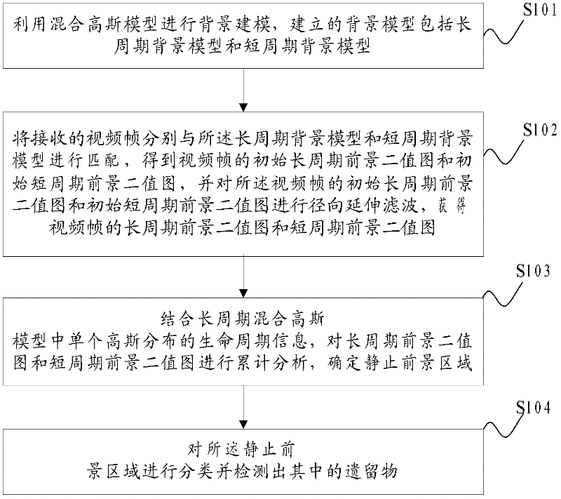
[0073] The method flow chart of Embodiment 1 of the residue detection method provided in the embodiment of the present application is as follows figure 1 shown, including:

[0074] Step S101: using a Gaussian mixture model for background modeling, and the established background model includes a long-period background model and a short-period background model;

[0075] The basic idea of ​​using Gaussian mixture model for background modeling is to regard pixels as independent random variables, and take the probability distribution of the pixel value of the pixel on the time axis P(X t ) is represented by a mixture of K independent Gaussian distributions, namely

[0076] P ( X t ) = Σ i = 1 K ω i , t * ...

Embodiment 2

[0163] The method flow chart of the second embodiment of the residue detection method provided in the embodiment of the present application is as follows Figure 5 As shown, before performing the method, detect the parent foreground area where the foreground area separation occurs in the short-period foreground binary image of each frame, and record the separation of the parent foreground area and several child foreground areas separated from the parent foreground area relationship, and track the several sub-foreground regions.

[0164] Such as Figure 6 as shown, Figure 6 It is a schematic diagram of two consecutive frames of foreground binary images where foreground area separation occurs;

[0165] Calculate the overlapping area of ​​the foreground area 2 and the foreground area 1, if the percentage of the area of ​​the overlapping area in the area of ​​the area area 2 is greater than the given fifth threshold condition, it is considered that the area 2 and the area 1 onc...

Embodiment 3

[0185] A schematic structural diagram of a remnant detection device provided in Embodiment 3 of the present application is as follows: Figure 7 shown, including:

[0186] Modeling module 701, radial extension filter 702, static foreground area detection module 703 and classification detection module 704;

[0187] The modeling module 701 is used to perform background modeling using a mixed Gaussian model, and the established background model includes a long-period background model and a short-period background model;

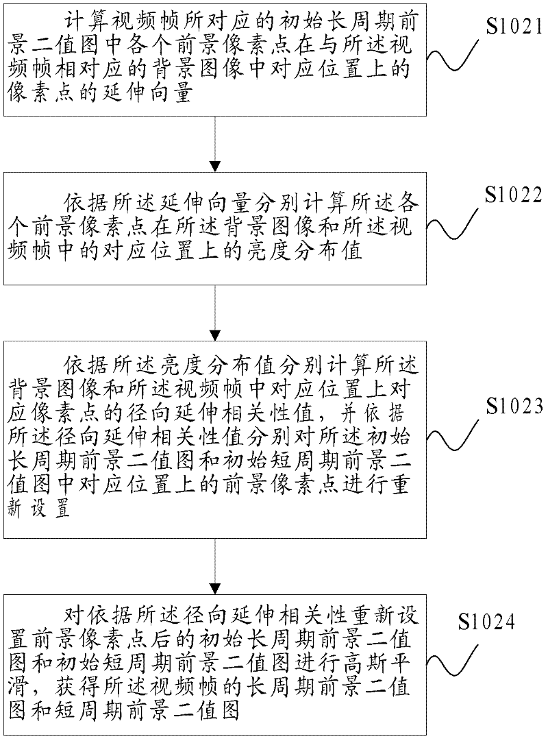
[0188] The radial extension filter 702 is used to match the received video frame with the long-period background model and the short-period background model respectively to obtain an initial long-period foreground binary image and an initial short-period foreground binary image of the video frame , and performing radial extension filtering on the initial long-period foreground binary image and the initial short-period foreground binary image of the video frame,...


PUM


Abstract

The invention discloses a remnant object detection method, which comprises the following steps: building a long-cycle background model and a short-cycle background model by a Gaussian mixture model; according to the background model, obtaining two foreground binary images of a video frame; respectively carrying out radial extending filtering on the two foreground binary images of the video frame to respectively obtain a long-cycle foreground binary image and a short-cycle foreground binary image of the video frame; obtaining single Gaussian-distribution life cycle information in a long-cycle Gaussian mixture model; carrying out cumulative analysis on the long-cycle foreground binary image and the short-cycle foreground binary image of the video frame in the life cycle; according to the life cycle information and a cumulative analysis result, determining a stationary foreground area; and detecting the stationary foreground area in a classified mode to detect remnant objects in the stationary foreground area. With the remnant object detection method, the remnant object detection precision is improved, and the false detection rate of the remnant object is lowered.

Description


Claims


Application Information

Patent Timeline
Owner CRSC COMM & INFORMATION GRP CO LTD
Why Eureka
Try Eureka