Switch cabinet status indicator with busbar temperature measurement, and measuring method thereof

A state indication and switch cabinet technology, applied in the field of power switch equipment, can solve the problems of many and complicated devices, large heat accumulation, economic loss, etc., and achieve the effect of simplifying hardware design structure, simplifying design structure, and strengthening anti-interference

Inactive Publication Date: 2012-06-20
ANHUI XINLONG ELECTRICAL
View PDF5 Cites 10 Cited by
  • Summary
  • Abstract
  • Description
  • Claims
  • Application Information

AI Technical Summary

Problems solved by technology

[0003] The traditional switchgear is assembled on the switchgear with discrete components such as a primary analog card, an electromagnetic switch status indicator, a grounding indicator, a live lockout indicator, and a heater fault monitor. , cannot dynamically indicate the state of the switchgear, cannot realize computer intelligent management, and it is difficult to realize more complex temperature and humidity control
At the same time, the current high-voltage switchgear operates at high voltage, high current and full load for a long time, and adopts a closed structure, which has poor heat dissipation effect and large heat accumulation. The safety of the cabinet, but the temperature of the heating part of the busbar cannot be monitored manually in real time, resulting in a fire accident, resulting in damage to the power equipment and affecting the normal operation of the system, which will cause huge economic losses

Method used


Image

  • Switch cabinet status indicator with busbar temperature measurement, and measuring method thereof
  • Switch cabinet status indicator with busbar temperature measurement, and measuring method thereof
  • Switch cabinet status indicator with busbar temperature measurement, and measuring method thereof

Examples


Embodiment Construction

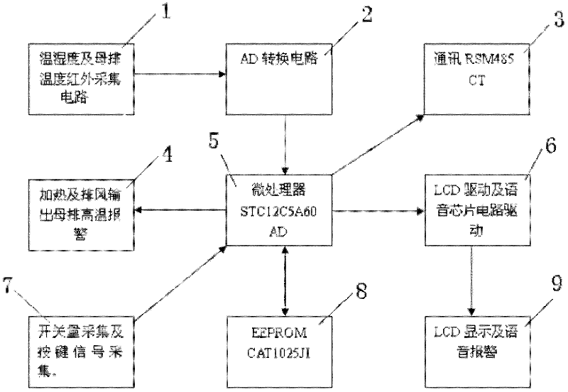
[0024] like figure 1 As shown, a switchgear status indicator with measuring busbar temperature, the switchgear status indicator, including a power supply connected to each circuit, a microprocessor 5, a display and voice drive circuit 6, temperature and humidity acquisition Circuit, infrared temperature acquisition circuit 1, switching value acquisition circuit 7, display, voice alarm circuit 9, human body induction circuit, control output circuit 4 and communication interface circuit 3, the temperature and humidity acquisition circuit, infrared temperature acquisition circuit 2 The A / D conversion circuit 2 and the microprocessor 5 are respectively connected with the display and voice drive circuit 6, the control output circuit 4, the communication interface circuit 3, and the memory 8, and the microprocessor 5 is also connected with the switch quantity acquisition Circuit 7 is connected with the human body induction circuit. The infrared temperature acquisition circuit is co...


PUM


Abstract

The invention discloses a switch cabinet status indicator with busbar temperature measurement, and a measuring method thereof. The switch cabinet status indicator is composed of a microprocessor, a liquid crystal display and voice driving circuit, a humiture acquisition circuit, an infrared temperature acquisition circuit, a switching value acquisition circuit, a display and voice alarm circuit, a human body induction circuit, a control output circuit and a communication interface circuit, wherein the humiture acquisition circuit and the infrared temperature acquisition circuit are respectively connected with the display and voice driving circuit, the control output circuit, the communication interface circuit and a memory through an A/D (Analog to Digital) conversion circuit and the microprocessor, and the microprocessor is also connected with the switching value acquisition circuit. By adopting the structure and method, not only indication of the on off status of a breaker of the switch cabinet is completed, but also the temperature of the busbar of the switch cabinet is tested by the infrared temperature measurement technique, the measured temperature value is judged and alarmed, the designed structure is simplified, and the reliability of products is improved.

Description

technical field [0001] The invention relates to power switchgear, in particular to a switchgear state indicator for measuring busbar temperature and a measuring method thereof. Background technique [0002] With the rapid development of my country's electric power industry, electric power equipment is developing in the direction of high integration, intelligence, and high reliability. The supply of electric power plays a very important role in the normal production and work of society. [0003] The traditional switchgear is assembled on the switchgear with discrete components such as a primary analog card, an electromagnetic switch status indicator, a grounding indicator, a live lockout indicator, and a heater fault monitor. , cannot dynamically indicate the state of the switchgear, cannot realize computer intelligent management, and it is difficult to realize more complex temperature and humidity control. At the same time, the current high-voltage switchgear operates at hi...

Claims


Application Information

Patent Timeline
Patent Type & Authority Applications(China)
IPC IPC(8): H02B15/04G01J5/00
Inventor 束龙胜陈坚伟秦小州汪桂林钱田义蒋丽丽
Owner ANHUI XINLONG ELECTRICAL
Why Eureka
Try Eureka