

Submerged electric arc current generating device
A technology for generating devices and arcs, applied to electric heating devices, electrical components, heating through discharge, etc., can solve problems such as unusable and inconvenient, and achieve the effects of improving use efficiency, saving waste, and improving utilization efficiency
- Summary
- Abstract
- Description
- Claims
- Application Information
AI Technical Summary
Problems solved by technology
Method used
Image

Examples
Embodiment 1
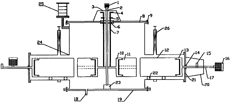
[0082] figure 1 Shown is a preferred embodiment of the submerged arc current generating device of the present invention.
[0083] Such as figure 1 As shown, the submerged arc flow generating device has a closed container as the reactor cylinder 24, which is made of stainless steel and can withstand high pressure and high temperature. The center of the container runs through a drive rod 2; the drive rod 2 passes through the center of the upper flange cover 8, and the center of the lower flange cover 19 at the bottom of the container is provided with a support 23, and the upper flange cover 8 and the support 23 jointly locate the drive rod 2, so as to Maintain the stable rotation of the drive rod 2. A seal 6 is arranged between the upper flange cover 8 and the driving rod 2 to ensure the sealing of the container. The upper flange cover 8 and the cylinder body 24 are fixed and sealed by hydraulic automatic lock 9 .
[0084] One end of the drive rod 2 on the outside of the con...
Embodiment 2
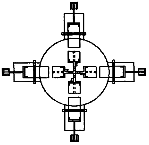
[0096] figure 2 Shown is a vertical submerged arc flow generating device.
[0097] Such as figure 2 As shown, the submerged arc flow generating device has a closed container as the reactor cylinder 24, which is made of stainless steel and can withstand high pressure and high temperature. The upper flange cover 8 of the container runs through a copper rod 17; after the copper rod 17 runs through the upper flange cover 8, one end in the cylinder body 24 is connected with a cathode electrode holder 13, and the electrode holder 13 is fixed with a cathode 12; The part of the rod 17 outside the cylinder body 24 is connected with a terminal post 15 . The copper rod 17 runs through the position of the upper flange cover 8 and is provided with a seal 14 .
[0098] The upper flange cover 8 of the container also runs through a copper rod 7; after the copper rod 7 penetrates the upper flange cover 8, an anode electrode holder 10 is connected to one end in the cylinder body 24, and th...
Embodiment 3
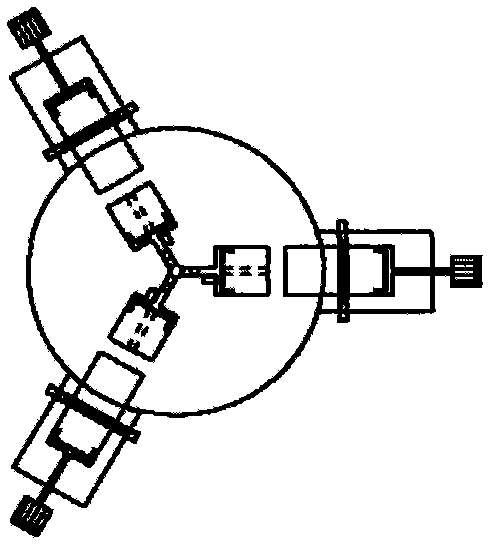
[0110] image 3 Shown is a horizontal submerged arc flow generating device.
[0111] Such as image 3 As shown, the submerged arc flow generating device has a closed container as the reactor cylinder 24, which is made of stainless steel and can withstand high pressure and high temperature. The cylinder body 24 is fixed on the base 30,
[0112] The upper flange cover 8 of the cylinder body 24 runs through a driving rod 2; a seal 6 is arranged between the upper flange cover 8 and the driving rod 2 to ensure the sealing of the container. The upper flange cover 8 and the cylinder body 24 are fixed and sealed by hydraulic automatic lock 9 .
[0113] One end of the drive rod 2 on the outside of the container (that is, outside the upper flange cover 8) is connected to the anode drive motor 1; in order to ensure the stable operation of the motor 1 and the drive rod 2, a support frame 3 is provided.
[0114] Inside the container, an anode electrode holder 10 is provided on the driv...
PUM
 Abstract
Description
Claims
Application Information