Embedded energy collector based on respiratory movement

An energy harvester and respiratory movement technology, applied in cardiac defibrillator, electrotherapy, treatment, etc., can solve the problems of skin infection, discomfort, and difficulty in aligning subcutaneous device sockets, etc., and achieve the effect of reducing physical burden

Active Publication Date: 2012-06-27
SHANGHAI JIAO TONG UNIV
View PDF2 Cites 7 Cited by
  • Summary
  • Abstract
  • Description
  • Claims
  • Application Information

AI Technical Summary

Problems solved by technology

This method creates a new idea for prolonging the service life of implantable devices, but its disadvantages are that the long-term probe insertion into the skin is prone to infection and discomfort, and the alignment of the subcutaneous device socket is also a major difficulty

Method used


Image

  • Embedded energy collector based on respiratory movement
  • Embedded energy collector based on respiratory movement
  • Embedded energy collector based on respiratory movement

Examples


Embodiment 1

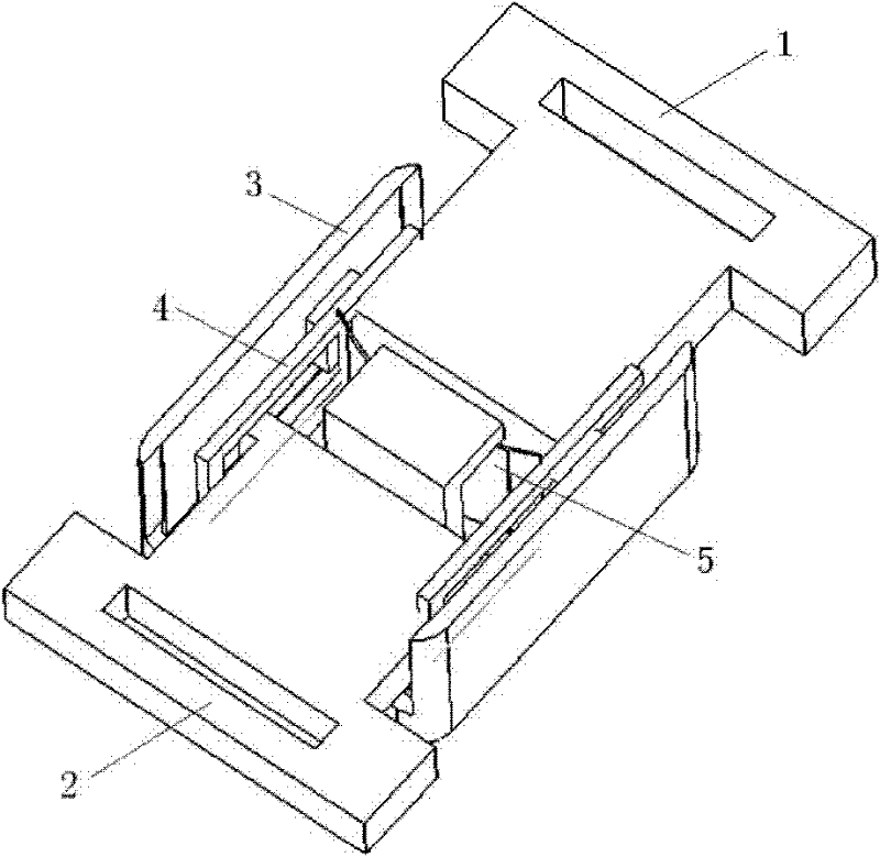
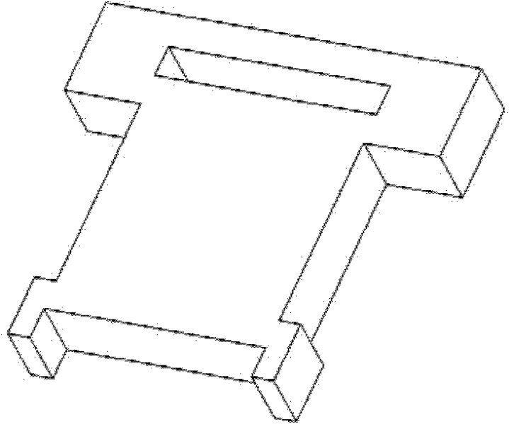
[0039] Such as figure 1 As shown, this embodiment includes a transducer, which is composed of a movable joint joint head, a bistable piezoelectric metal sheet 5, a positioning guide rail 4 and a packaging shell 3; the positioning guide rail 4 is fixedly installed on the packaging shell 3 above, it is slidingly matched with the movable joint joint, and the movable joint joint can only slide back and forth along the direction of the guide rail 4; the bistable piezoelectric metal sheet 5 is located in the middle of the two movable joint joints, and the two The two sides are respectively connected with the movable joint joint head; the positioning guide rail 4 and the packaging shell 3 are located on both sides of the movable joint joint head. The overall size of this embodiment is 18 millimeters * 10 millimeters * 5 millimeters.

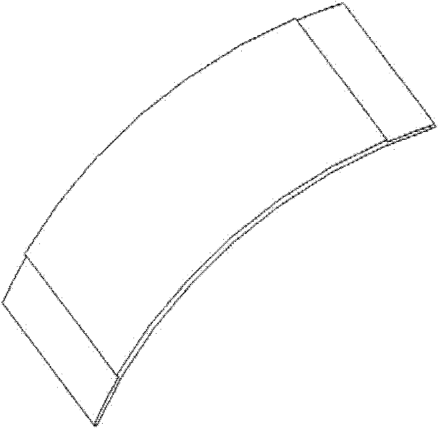
[0040] Such as Figure 3-4 As shown, in the present embodiment, the joint ribs and the movable joint joint of the piezoelectric sheet;

[0041] The ...

Embodiment 2

[0052] Such as Figure 7 As shown, this embodiment includes a movable joint joint head, a bistable piezoelectric metal sheet 5, a positioning guide rail 4 and a packaging shell 3, and the connection method is the same as that of the first embodiment. The overall size of this embodiment is 20 millimeters * 12 millimeters * 5 millimeters.

[0053] Such as Figure 9 As shown in the figure, the flexible joint joint connecting the ribs and the piezoelectric sheet; wherein the material of the joint joint is Teflon plastic. There are two movable joint joints in a group, and the two ends of one joint are at an angle of 90 degrees, and the other joint is fixedly connected on the shell 3 . The connecting heads 1 and 2 have a certain degree of flexibility, can be bent, and have a length of 9 millimeters, and are connected with the piezoelectric sheet in a two-finger shape with a gap of 8 millimeters.

[0054] Each connecting part of the connecting head is a non-fixed connection with a...

Embodiment 3

[0063] Such as Figure 12 As shown, this embodiment includes: a movable joint joint head, a bistable piezoelectric metal sheet 5 , a positioning guide rail 4 and a packaging shell 3 . The connection mode is the same as the embodiment. The overall size of this embodiment is 20 millimeters * 12 millimeters * 5 millimeters.

[0064] Such as Figure 14 As shown, in this embodiment, the flexible joint joints of the joint ribs and piezoelectric sheets, wherein the material of the joint joints is Teflon plastic. There are two movable joint joints in a group, the two ends of one joint are at an angle of 90 degrees, and the other joint is fixedly connected to the shell. The connecting head has a certain degree of flexibility and is bendable, with a length of 8 millimeters, and the connecting part with the piezoelectric sheet is connected in a two-finger shape with a gap of 8 millimeters.

[0065] Each connection part of the connection joint is a non-fixed connection with a certain ...


PUM


Abstract

The invention discloses an embedded energy collector based on respiratory movement, which comprises an energy converter. The energy converter is mainly formed of a movable linkage joint, a bistable-state piezoelectric metal sheet, a location guide rail and a package casing. The location guide rail is fixed on the package casing to be in slide fit with the movable linkage joint, the bistable-state piezoelectric metal sheet, two sides of the bistable-state piezoelectric metal sheet are respectively connected with the movable linkage joint, and the location guide rail and the package casing are arranged on two sides of the movable linkage joint. Two movable ends of the energy converter are fixed on two adjacent ribs. When a user breathes, gaps between ribs are led to be changeable by expansion and extraction of chest cavities to drive a cross linkage joint to enable the bistable-state piezoelectric metal sheet to generate continuous current periodically. The embedded energy collector based on respiratory movement can achieve permanent stable energy supply of embedded equipment in human chest cavities, and simultaneously is small in volume and capable of reducing body loads of patients and avoiding secondary operations for replacing batteries after the embedded equipment is embedded.

Description

technical field [0001] The present invention relates to an energy harvester in the technical field of medical devices, in particular to an implantable energy harvester based on breathing motion. Background technique [0002] Implantable pacemakers or defibrillators keep millions of heart patients sick. Such devices generally consist of two parts, a pulse generator and a battery. Batteries used in implantable medical electronic devices cannot be replaced at will. Before the implantable medical electronic device is sealed, the battery is held securely inside it. Since then, the implanted battery has been powering the device during the side-testing phase of the implanted medical electronic device, during the storage phase, and after implantation in the human body. Therefore, the service life of the battery in the implanted device determines the service life of the device. Generally, the working life of a cardiac pacemaker is 5 to 10 years, and the implanted battery is require...

Claims


Application Information

Patent Timeline
Patent Type & Authority Applications(China)
IPC IPC(8): A61N1/378A61N1/39
Inventor 刘景全何庆田鸿昌杨春生李以贵
Owner SHANGHAI JIAO TONG UNIV
Why Eureka
Try Eureka