High-speed spindle with tapered hole capable of being automatically locked

An automatic locking, high-speed spindle technology, used in metal processing equipment and other directions, can solve the problems of increased wear of the shank taper, excessive bearing preload, increased flexibility of the shank taper, etc., and achieve high radial positioning. Accuracy, increase the stiffness of the connection, and increase the effect of the limit speed

Inactive Publication Date: 2012-06-27
YANSHAN UNIV
View PDF6 Cites 9 Cited by
  • Summary
  • Abstract
  • Description
  • Claims
  • Application Information

AI Technical Summary

Problems solved by technology

For the existing HSK tool holder and spindle, the contradiction between the connection stiffness and the rotational speed is an unsolvable problem: increasing the fit interference between the tool holder and the spindle is beneficial to increase the rotational speed, but a large interference will make the tool The tension of the shank is difficult, which increases the tension of the tie rod, resulting in increased wear on the tapered surface of the shank; after the shank is tightened, the large interference will cause the radial expansion of the end of the spindle, and the expansion of the spindle will cause the spindle to move forward. The inner ring of the bearing expands, resulting in excessive preload of the bearing, which significantly reduces the service life; at the same time, the large interference reduces the clamping force transmitted to the end face of the tool holder, and reduces the radial connection stiffness between the tool holder and the spindle
A small interference is beneficial to improve the radial stiffness, but a small interference will make it easier to produce a gap between the taper surface of the tool holder and the spindle during high-speed machining, which will cause the loss of the positioning accuracy of the tool holder and limit the tool holder. Shank limit speed
To sum up, the hollow structure makes the flexibility of the taper surface of the tool holder limited, and the interference cannot be compensated with the change of the speed
With the increase of the speed, the fit interference of the taper surface gradually decreases until a gap is generated, the radial positioning effect is lost, and processing cannot be performed. The existing machine tool spindle can generate a high speed, and modern processing technology is moving towards high speed and ultra high speed. With the development, the limit speed of the tool holder has become the main factor limiting the increase of the speed of high-speed machining

Method used


Image

  • High-speed spindle with tapered hole capable of being automatically locked
  • High-speed spindle with tapered hole capable of being automatically locked
  • High-speed spindle with tapered hole capable of being automatically locked

Examples


Embodiment 1

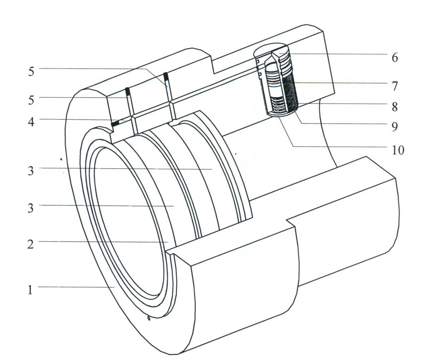
[0014] exist figure 1 In the schematic diagram of the high-speed spindle structure with tapered holes that can be automatically locked, the inner hole of the shaft end of the spindle 1 is fixedly connected with the expansion wall 2 with a tapered hole through an interference fit. The taper of the expansion wall taper hole is 1:10. Two annular oil chambers 3 are opened on the outer surface of the expansion wall, and the oil chambers are filled with liquid medium (such as hydraulic oil). There are two radial hydraulic cylinder installation blind holes on the outer surface of the main shaft, and the two blind holes are symmetrically distributed with respect to the main shaft axis. Two axial oil passages 4 are opened on the end surface of the main shaft in the axial direction, respectively communicating with the above two symmetrical blind holes, and the openings of the oil passages on the end surface of the main shaft are sealed. The main shaft is provided with a radial oil pass...

Embodiment 2

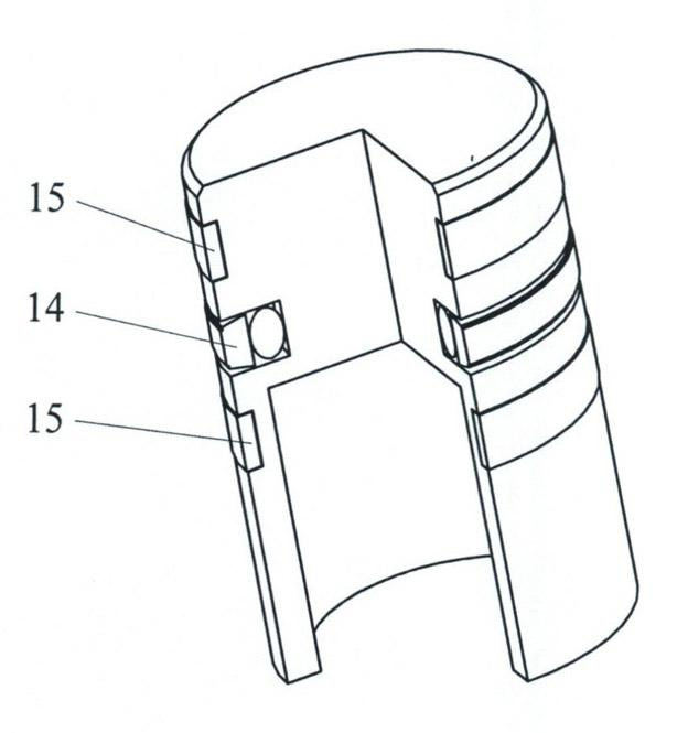
[0016] Its structure is the same as embodiment 1, and the piston is a stepped cylinder, such as Figure 4 shown.

[0017] The oil passages on each side of the main shaft are connected to an oil cavity through their respective radial oil passages, and the oil passages on both sides of the main shaft are not connected.


PUM


Abstract

The invention provides a high-speed spindle with tapered hole capable of being automatically locked. The high-speed spindle comprises a spindle, an expansion wall, hydraulic cylinders and an oil path and is characterized in that: an inner hole at the shaft end of the spindle is fixedly linked with the expansion wall with the tapered hole through interference fit; two oil cavities are disposed on the outer surface of the expansion wall; a liquid medium is filled in the oil cavities; two sets of the hydraulic cylinders consisting of a cylinder body component and a piston are symmetrically arranged on the spindle with respect to the axis of the spindle; the cylinder body components are communicated with the oil cavities through the oil path; and a spring is arranged at the bottom of each piston. The high-speed spindle disclosed by the invention has the advantages that: the magnitude of the interference fit between the tapered surface of the knife handle and the tapered hole of the spindle is subjected to automatic compensation. Furthermore, the compensation amount is increased when a rotation speed is increased. The linkage rigidness and the positioning precision of the knife handle and the spindle are ensured at any rotation speed, and the limit rotation speed is improved. The deformation coaxiality generated by the expansion wall is very high, so that the good radial position precision can be ensured. The liquid medium can supply great damping, the power absorbers consist of the piston and the spring, so that the two have vibration absorption effects on the spindle.

Description

technical field [0001] The invention relates to the field of machine tool spindles, in particular to a high-speed spindle with a taper hole connected to a tool holder. Background technique [0002] The high-speed spindle is the key component to achieve high-speed machining. The basic function of the spindle taper is to ensure the positioning accuracy of the tool holder in the machine tool spindle, and keep it unchanged during high-speed machining, while transmitting the motion and power required for machining. The traditional tool holder is a solid structure with a taper of 7:24, which is positioned on one side of the taper. At high speed, the taper hole of the spindle will expand in a "bell mouth" shape due to centrifugal force, and there will be a gap between the taper surface of the tool holder, which cannot meet the requirements of high-speed machining. In order to meet the needs of high-speed machining, several high-speed tool holders have appeared in foreign countries...

Claims


Application Information

Patent Timeline
Patent Type & Authority Applications(China)
IPC IPC(8): B23B19/02
Inventor 王军唐建军
Owner YANSHAN UNIV
Why Eureka
Try Eureka