Coupling method for servo motor shaft and rotor

A servo motor and motor shaft technology, applied in the manufacture of motor generators, electrical components, electromechanical devices, etc., can solve the problems of high manufacturing cost, motor heating control accuracy, decline, etc., to reduce assembly costs, high connection accuracy, and reduced cost effect

Inactive Publication Date: 2013-01-23
HARBIN INST OF TECH
View PDF0 Cites 0 Cited by
  • Summary
  • Abstract
  • Description
  • Claims
  • Application Information

AI Technical Summary

Problems solved by technology

There are three main disadvantages of this connection structure: 1. Due to the use of clearance fit, the center of mass of the motor shaft and the center of mass of the motor rotor must not coincide, and additional torque will be generated when the motor rotates, resulting in tremors during high-speed operation, motor heating and control accuracy. 2. Since the main component of the adhesive is resin, there is inevitably an aging problem; 3. In order to control the misalignment of the center of mass within a certain range, a high-precision fixture should be used to ensure that the high-precision Fixture manufacturing costs are relatively high

Method used


Image

  • Coupling method for servo motor shaft and rotor
  • Coupling method for servo motor shaft and rotor

Examples


Embodiment Construction

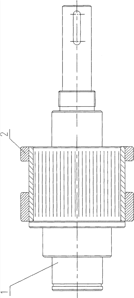
[0023] refer to figure 1 As shown, a connection structure with reasonable structure, higher connection precision, connection rigidity and connection reliability, and effective cost reduction includes a servo motor shaft 1 and a servo motor rotor 2 . Among them, the servo motor rotor 2 and the special adhesive are provided by the servo motor manufacturer, and the tolerance of the matching hole of the servo motor rotor is about φD(H 7 ). The characteristic of the servo motor shaft 1 is that the matching part with the servo motor rotor 2 has a straight roller flower groove or a milled triangular groove, and has strict matching accuracy requirements. The processing technology of this part is as follows: after semi-finishing, the diameter dimension φD leaves 0.2~0.3 grinding allowance; straight roll t=2~3 (2mm before and after the mating part without rolling), the knurling depth is not less than 1mm; fine grinding Up to the dimensional accuracy requirement φD(n6), and the depth o...


PUM


Abstract

The invention discloses a coupling structure for a servo motor rotor and a servo motor shaft. The servo motor rotor (2) and a special adhesive are provided by a servo motor manufacturer, wherein the tolerance of a servo motor rotor matching hole is phi D (H7). A straight roller spline is reserved at the matching position of the servo motor shaft (1) and the servo motor rotor (2). When assembling the servo motor, a coupling method for the servo motor rotor and the servo motor shaft comprises the following steps of: first, boiling the servo motor rotor (2) in boiling water for 5 to 10 minutes; cleaning the matching surface of the motor shaft (1) at the same time; and coating a thin layer of the adhesive on the surface uniformly; then, taking the servo motor rotor (2) out of the boiling water, and after water drops on the surface evaporate, sleeving the servo motor rotor (2) on a corresponding part of the servo motor shaft (1) rapidly and pressing the servo motor rotor (2) in place by using a bench vice; and finally, after cooling, performing a solidifying process by using the adhesive. The coupling structure has the characteristics of reasonable structure and higher coupling precision, coupling rigid and coupling reliability, and can effectively reduce cost.

Description

technical field [0001] The invention relates to a servo motor shaft and rotor with higher connection precision, connection rigidity and connection reliability, and effective cost reduction compared with the traditional servo motor shaft and motor rotor connection method in the field of precision machinery manufacturing. connection method. Background technique [0002] When purchasing and using a shellless servo motor, the connection method between the motor shaft (made by the user) and the motor rotor is generally provided by the manufacturer of the servo motor. The most commonly used connection method is: using H 7 / h 6 Level gap fit, and fill the gap with the adhesive provided by the motor manufacturer. There are three main disadvantages of this connection structure: 1. Due to the use of clearance fit, the center of mass of the motor shaft and the center of mass of the motor rotor must not coincide, and additional torque will be generated when the motor rotates, resulti...

Claims


Application Information

Patent Timeline
Patent Type & Authority Patents(China)
IPC IPC(8): H02K15/00
Inventor 刘延杰吴明月荣伟彬孙立宁
Owner HARBIN INST OF TECH
Why Eureka
Try Eureka