
Guard strip plate locking device

A locking device, technology of strips

Inactive Publication Date: 2012-06-27
JIANGSU JINFEIDA POWER TOOLS
View PDF5 Cites 0 Cited by
  • Summary
  • Abstract
  • Description
  • Claims
  • Application Information

AI Technical Summary

Problems solved by technology

Although the above-mentioned installation method can ensure the convenience and rapidity of the installation and disassembly of the protective strip, there are potential safety hazards: for example, the protective strip is easy to fall due to misoperation without the use of external tools; and, Due to the vibration of the power tool itself, the guard strip will naturally slide off

Method used


Image

  • Guard strip plate locking device
  • Guard strip plate locking device
  • Guard strip plate locking device

Examples


Embodiment Construction

[0013] The present invention will be further described below in conjunction with the accompanying drawings.

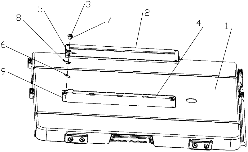
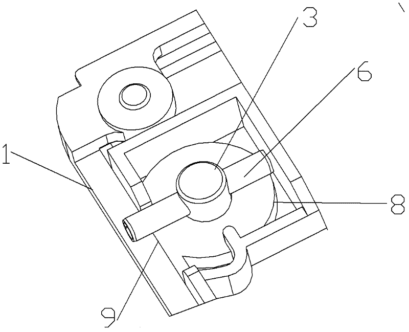
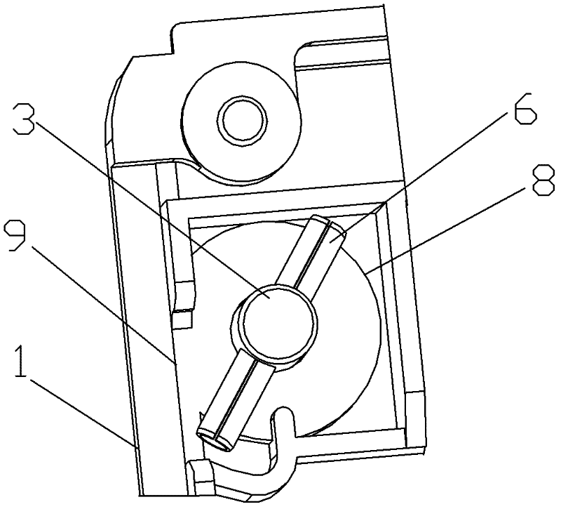
[0014] Such as Figure 1 to Figure 3 As shown, a kind of guard strip locking device of the present invention comprises workbench 1, guard strip 2 and locking screw 3, and guard strip 2 is placed in the groove 4 of workbench 1, and each guard strip 2 A round hole 5 is provided at the top corner, and the locking screw 3 passes through the round hole 5 and extends into the bottom of the workbench 1. The end of the locking screw 3 is provided with a through hole 7 for inserting the elastic pin 6; in the locked state, the elastic pin 6 is inserted into the through hole 7 and one end of the elastic pin 6 exceeds the edge 9 of the groove 4 of the workbench 1 so that the guard strip 2 is clamped on the workbench 1 . Usually, a wave washer 8 is provided on the locking screw 3 , and the wave washer 8 is located between the guard strip 2 and the elastic pin 6 .

[0015] During ...


PUM


Abstract

The invention discloses a guard strip plate locking device, which comprises a workbench, a guard strip plate and locking screws, wherein the guard strip plate is arranged in a groove of the workbench, each vertex angle of the guard strip plate is provided with a circular hole, each locking screw penetrates through a circular hole and extends to a position below the workbench, and the tail end of each locking screw is provided with a through hole for inserting an elastic pin; and in a locking state, the elastic pin is inserted into the through hole, and one end of the elastic pin exceeds the edge of the groove of the workbench, so that the guard strip plate is clamped on the workbench. The device overcomes the prejudice of those skilled in the prior art; quickness and convenience of assembly and disassembly of the guard strip plate are considered, and the safety of the guard strip plate is more stressed; the workbench, the guard strip plate, the locking screws and the elastic pins are used as locking components and mutually matched; the positions of the elastic pins are adjusted by using a tool to effectively lock the guard strip plate, so that the safety performance can be greatly improved; and moreover, because excessive locking pieces are not increased, the guard strip plate is very convenient to assemble and disassemble.

Description

technical field [0001] The invention relates to a guard strip of an electric tool, in particular to a locking device for the guard strip. Background technique [0002] At present, table saws, woodworking saws, miter saws, compound saws, etc. are common electric cutting tools and are widely used in the field of machinery manufacturing. These electric cutting tools all include a saw blade. Usually, a part of the saw blade is located in the workbench, while the other part is exposed from the workbench so as to cut wood, plastic and other articles. In order to protect the saw blade and ensure safety, guard strips are installed on the workbenches of the existing electric cutting tools. [0003] In the prior art, when installing the guard strips on the workbench, people first consider the convenience and rapidity of installation and disassembly. The existing guard strips are usually embedded in the groove of the workbench and installed by pressing or pressing; or they are instal...

Claims


Application Information

Patent Timeline
IPC IPC(8): B23D59/00
Inventor 张庆奇朱金宝
Owner JIANGSU JINFEIDA POWER TOOLS
Learn More