Panel feeding clamp

A sheet material and material feeding technology, which is applied in metal processing and other directions, can solve problems affecting work efficiency and achieve the effect of stable clamping force

Active Publication Date: 2012-06-27
爱克(苏州)机械有限公司
View PDF5 Cites 11 Cited by
  • Summary
  • Abstract
  • Description
  • Claims
  • Application Information

AI Technical Summary

Problems solved by technology

[0002]In the traditional technology, the sheet material feeding clamp is mostly controlled by the air cylinder, hydraulic cylinder or electric pull rod to keep the sheet clamped. or power failure to force the work to terminate, seriously affecting work efficiency

Method used


Image

  • Panel feeding clamp
  • Panel feeding clamp
  • Panel feeding clamp

Examples


Embodiment Construction

[0017] The technical scheme of the present invention is described in detail below in conjunction with the embodiment shown in the accompanying drawings:

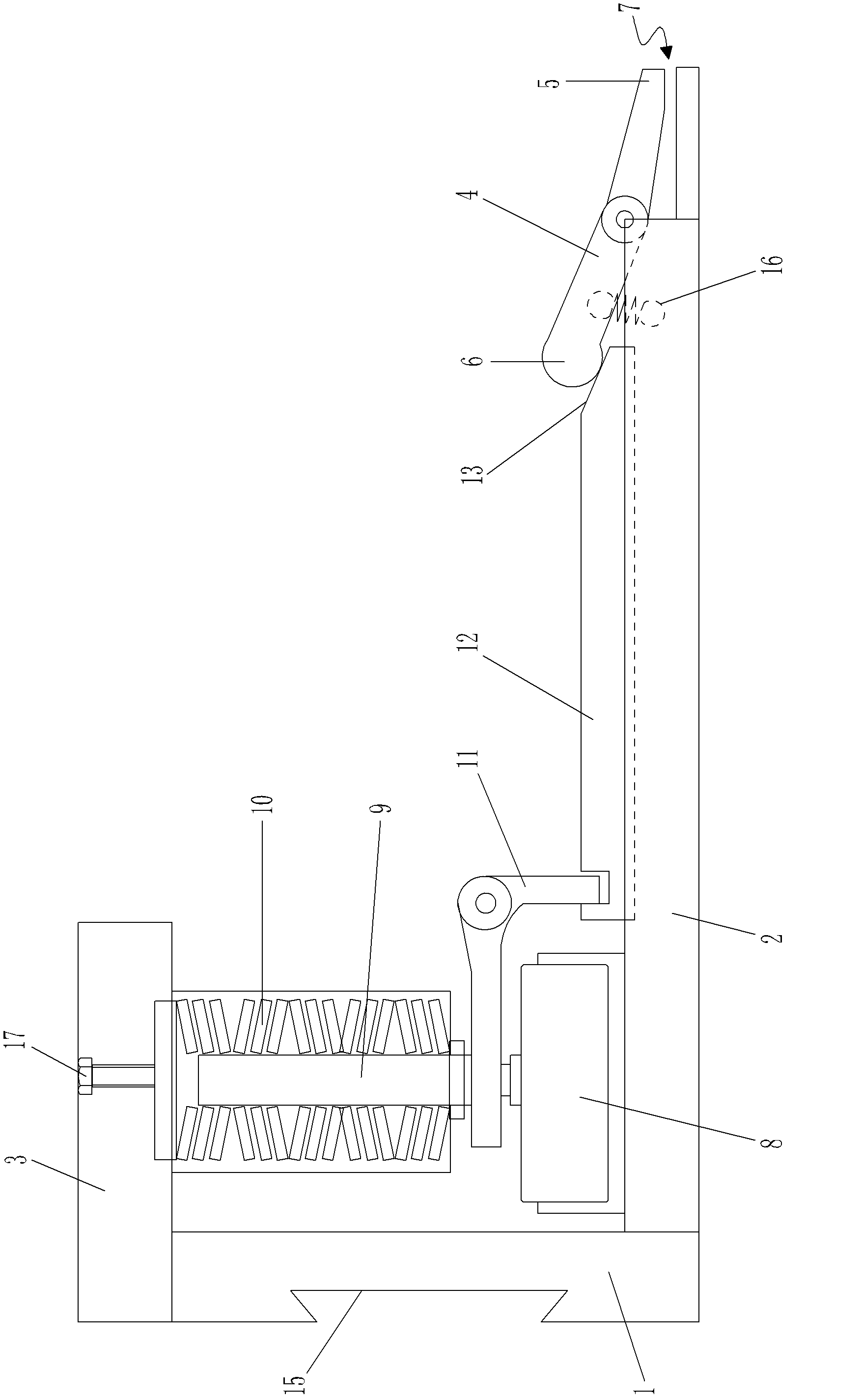
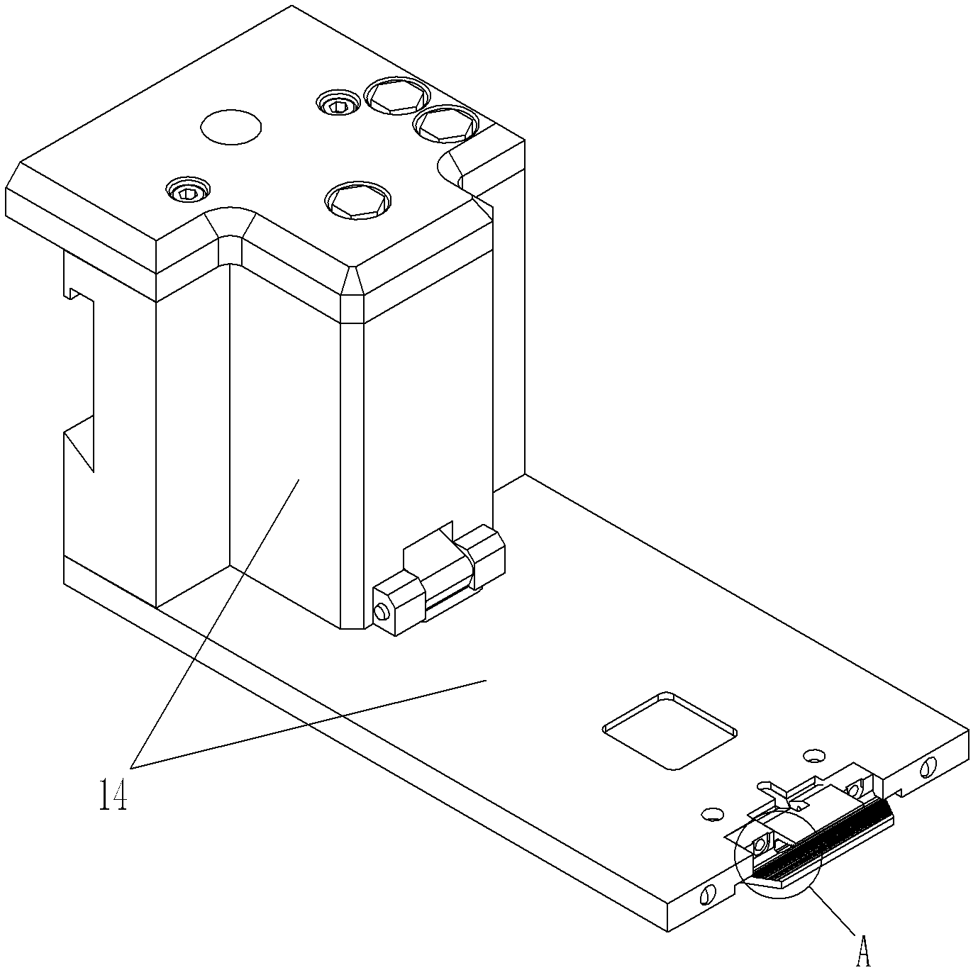
[0018] as attached figure 1 and attached figure 2 As shown, the plate feeding clamp of the present invention includes a base 1 for external installation, a clamp base 2 fixed on the base 1 at one end, a base plate 3 fixed on the base 1, and another hinged on the clamp base 2 in the middle. The pressure rod 4 at one end and the outer shell 14 are covered. The pressure rod 4 has a jaw end 5 forming the jaw 7 with the clamp base 2, and a non-pliers that realizes the opening or closing of the jaw 7 by the control of the driving mechanism. The mouth end 6, the driving mechanism includes a cylinder 8 arranged on the clamp base 2, a spring assembly arranged on the base plate 3, the cylinder 8 is connected with the spring assembly, and the force direction of the spring assembly is on the same line as that of the cylinder 8 ...


PUM


Abstract

The invention discloses a panel feeding clamp, which comprises a base for external installation, a pincer seat with one end fixed on the base, a substrate fixed on the base, a compression bar with the middle hinged with the other end of the pincer seat and an external casing. The compression bar is provided with a pincer opening end and a non-pincer opening end, wherein the pincer opening end andthe pincer seat form a pincer opening, and the non-pincer opening end is controlled by a driving mechanism to achieve opening or closing of the pincer opening, the driving mechanism comprises a cylinder arranged on the pincer seat and a spring assembly arranged on the substrate, the cylinder is connected with the spring assembly, the casing is rotatably provided with a C-shaped crank arm, one endof the crank arm is hinged to a connection portion of the cylinder and the spring assembly, the other end of the crank arm is hinged to a connection plate capable of sliding along the surface of the pincer seat, and elasticity effects of the spring assembly drive the connection plate to move close to the compression bar to enable the pincer opening to clamp a panel through the crank arm. When thecylinder applies reverse force on the crank arm, the crank arm drives the connection plate to move far away from the compression bar to enable the pincer opening to open. The clamp force is stable and reliable, has no damage to the surface of the panel, and avoids influences of power-down, decompression or pressure oscillation.

Description

technical field [0001] The invention relates to a sheet material feeding clamp. Background technique [0002] In the traditional technology, the sheet material feeding clamps are mostly controlled by air cylinders, hydraulic cylinders or electric pull rods to keep clamping the sheets. However, such implementation methods often force the work to be terminated due to pressure loss, pressure fluctuations, or power failures, seriously affecting work efficiency. Contents of the invention [0003] The object of the present invention is to provide a feed clamp which is driven by a spring assembly to provide the action of a clamp, capable of reliably clamping a sheet material. [0004] In order to solve the problems of the technologies described above, the present invention adopts the following technical solutions: [0005] A sheet material feeding clamp, comprising a base for external installation, a clamp base fixed on the base at one end, a base plate fixed on the base, and an...

Claims


Application Information

Patent Timeline
Patent Type & Authority Applications(China)
IPC IPC(8): B23Q7/00
Inventor 蔡国华李彬朱卫东孙建民
Owner 爱克(苏州)机械有限公司
Why Eureka
Try Eureka