
Navigation mark with annular phased-array radar

A ring-shaped phased array and phased array antenna technology, applied in the field of navigation marks, can solve the problems of high power consumption of the mechanical rotating drive mechanism, inability to scan the surrounding environment, easy failure of the rotating mechanism, etc. The effect of improving reliability

Inactive Publication Date: 2012-06-27
WUHAN UNIV OF TECH
View PDF6 Cites 2 Cited by
  • Summary
  • Abstract
  • Description
  • Claims
  • Application Information

AI Technical Summary

Benefits of technology

This technology improves the efficiency and accuracy of navigating vessels through radio signals transmitted between them. It uses less powerful components than traditional methods while still maintaining its effectiveness for safe operation. Additionally, it reduces damage caused during use due to metal parts attached to the surface or other devices used inside the ship's structure without requiring frequent maintenance. Overall, this innovative solution provides technical benefits such as reducing fuel usage, enhancing security measures, increasing signal-to-noise ratio (SNR), making communication more reliable over longer distances, and decreasing costs associated therewith.

Problems solved by technology

This patented describes an improved radio-navigation system called Radio Navigation Mark (RML). It uses multiple sensors placed close together along certain lines to help navigate through difficult areas like rivers without damaging them. However, current systems use expensive machinery such as motors and gears, making it hard to maintain consistence over longer periods due to wear caused by weather conditions. Additionally, these existing designs have limited range resolution and may be unsafe when exposed during operation.

Method used


Image

  • Navigation mark with annular phased-array radar
  • Navigation mark with annular phased-array radar
  • Navigation mark with annular phased-array radar

Examples


Embodiment Construction

[0022] Embodiments of the present invention will be further described below in conjunction with the accompanying drawings.

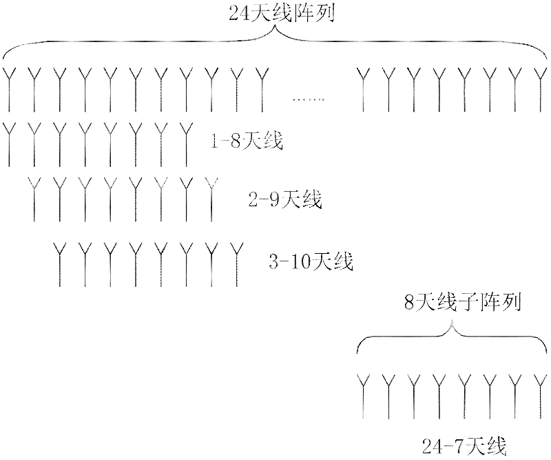
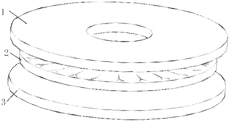
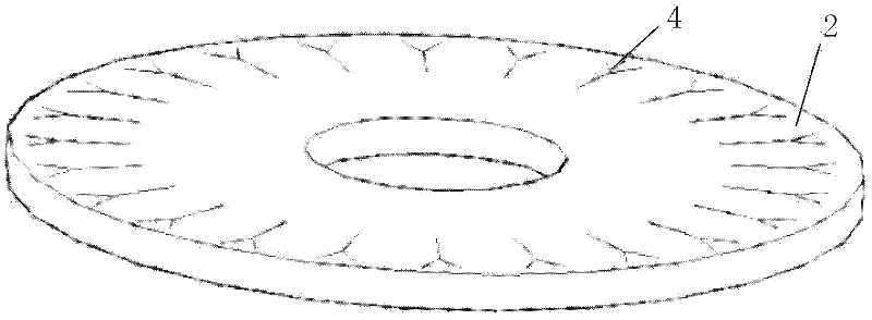
[0023] see image 3 and Figure 5 , a navigation mark 6 with annular phased array radar, comprising a navigation mark ship 7, a navigation mark tower, a phased array antenna layer 2 and a navigation mark light 5 are sequentially arranged on the navigation mark ship 7; the phased array antenna layer 2 is composed of Composed of 24 phased array antennas 4, 24 phased array antennas 4 are arranged on the beacon tower around the beacon tower, that is, installed under the beacon light 5; the transmitting and receiving unit of the phased array antenna layer is synthesized The beam composed of electromagnetic waves covers 360°, and the beam crossing position is not lower than 3dB at the center of the main lobe.

[0024] In order to avoid unnecessary waste of resources, the transmission power of the phased array antenna layer 2 directed to the channel is 2 to 1...


PUM


Abstract

The invention relates to a navigation mark with an annular phased-array radar, comprising a navigation-mark ship, wherein a navigation-mark lamp and a navigation-mark tower are disposed on the navigation-mark ship, and the navigation-mark lamp is connected with the navigation-mark ship via the navigation-mark tower. The navigation mark with an annular phased-array radar further comprises a phased-array radar with a plurality of phased-array antennas, wherein the phased-array antennas are disposed on the navigation-mark tower around the navigation-mark tower to form an annular phased-array antenna layer. The navigation mark disclosed by the invention has the following advantages that: 1, a radar navigation mark low in energy consumption and high in reliability is provided, and via the radar navigation mark, ships know the situations of ships and channels around water body, so that the ships smoothly finish navigation, and safety is ensured; 2, the phased-array antenna layer is fixed below the navigation-mark lamp, and by means of static fixation, the rotation wear of mechanical device and circuit is reduced, the reliability of radar is enhanced, and the cost of radar is decreased; and 3, metal discs are installed on the upper surface and the lower surface of the phased-array antenna layer, and used for preventing electromagnetic wave from being absorbed by water body, so that the gains of phased-array antennas are increased.

Description


Claims


Application Information

Patent Timeline
Owner WUHAN UNIV OF TECH
Learn More