Laminated cell side surface adhesive tape sticking device

A gluing device and gluing technology are applied in transportation and packaging, electrolyte storage battery manufacturing, non-aqueous electrolyte storage batteries, etc., which can solve the problems of easy deformation of batteries, large deformation rate, and small restriction effect of formed batteries, and achieve gluing efficiency. High, ensure stability, ensure accuracy and the effect of the success rate of the glue

Active Publication Date: 2012-06-27
深圳市和合自动化有限公司
View PDF6 Cites 32 Cited by
  • Summary
  • Abstract
  • Description
  • Claims
  • Application Information

AI Technical Summary

Problems solved by technology

[0002] Gluing at the end is one of the technical difficulties of battery lamination equipment. Generally, glue is applied to the middle of the laminated cells after the finishing to prevent the cells from unraveling after winding and forming, and glue is applied to the bottom to prevent the inside of the cells. The contact between the bottom of the positive plate and the battery case causes a short circuit of the battery, and the gluing mechanism for the middle and bottom gluing is simple, but it has little restriction on the forming of the battery, and the battery is easy to deform, especially for large-scale batteries, with a large deformation rate

Method used


Image

  • Laminated cell side surface adhesive tape sticking device
  • Laminated cell side surface adhesive tape sticking device
  • Laminated cell side surface adhesive tape sticking device

Examples


Embodiment Construction

[0029] The present invention will be further described in detail below through embodiments in conjunction with the accompanying drawings.

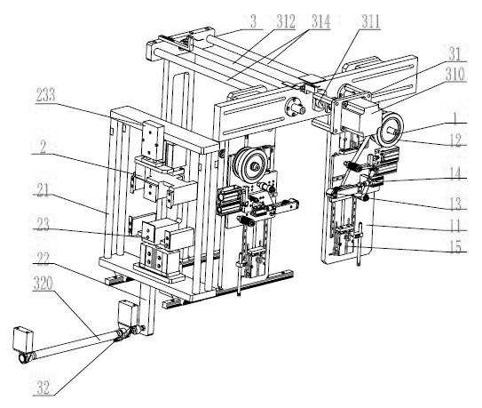
[0030] refer to Figure 1-Figure 7 , in one embodiment, the side gluing device of laminated cells includes a gluing mechanism 1 , a gluing fixing mechanism 2 and a moving mechanism 3 .

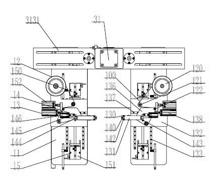
[0031] Such as figure 1 and image 3 As shown, the gluing mechanism 1 includes two sets of gluing components arranged oppositely, and a space for the gluing fixing mechanism 2 to enter is left between the two sets of gluing components.

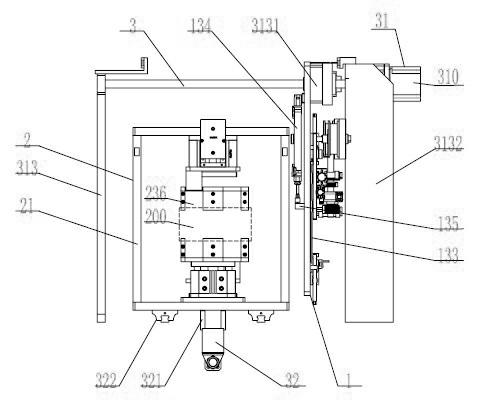
[0032] Such as figure 1 and figure 2 As shown, the adhesive fixing mechanism 2 includes two sets of clamping units 23 arranged oppositely, which are used to clamp the laminated battery cell 200 and expose at least a part of the side of the laminated battery cell and the side of the top end connected to the corresponding side and bottom side.

[0033] Such as figure 1 As shown, the moving mechanism 3 includes a glui...


PUM


Abstract

The invention discloses a laminated cell side surface adhesive tape sticking device, which comprises an adhesive tape sticking mechanism, an adhesive tape fixing mechanism and a moving mechanism. The adhesive tape sticking mechanism comprises two groups of adhesive tape sticking components which are arranged to be opposite one another. A space for the adhesive tape fixing mechanism to enter is left between the adhesive tape sticking components. The adhesive tape fixing mechanism comprises two groups of clamping units which are arranged to be opposite one another and is used for clamping a laminated cell and exposing at least partial side surface of the laminated cell and the side parts of a top end and a bottom end which are connected with the corresponding side surfaces. The moving mechanism comprises a clamping moving unit which is used for driving the adhesive tape fixing mechanism and an adhesive tape sticking moving unit which is used for driving the adhesive tape sticking mechanism. After the adhesive tape sticking mechanism is configured, the adhesive tape sticking mechanism drives the adhesive tape sticking components at an adhesive tape sticking position to stick an adhesive tape from the side part of the top end to the side part of the bottom end of the laminated cell along the side surface of the laminated cell, or from the side part of the bottom end to the side part of the top end of the laminated cell. The adhesive tape sticking device has the advantages that the adhesive tape sticking success rate is high, especially the laminated cell can be prevented from being deformed, the stability of the laminated cell can be guaranteed and the quality of the laminated cell is improved.

Description

technical field [0001] The invention relates to battery manufacturing equipment, in particular to a side gluing device for laminated battery cells. Background technique [0002] Gluing at the end is one of the technical difficulties of battery lamination equipment. Generally, glue is applied to the middle of the laminated cells after finishing to prevent the cells from opening after winding and forming, and glue is applied to the bottom to prevent the inside of the cells. The contact between the bottom of the positive plate and the battery case causes the short circuit of the battery. The gluing mechanism for the middle and bottom gluing is simple, but it has little restriction on the forming of the battery, and the battery is easy to deform, especially for large-scale batteries, with a large deformation rate. Contents of the invention [0003] The main purpose of the present invention is to address the shortcomings of the prior art and provide a side gluing device for lam...

Claims


Application Information

Patent Timeline
Patent Type & Authority Applications(China)
IPC IPC(8): B65H37/04H01M10/058
CPCY02E60/12Y02E60/10Y02P70/50
Inventor 王胜玲罗捷王维东
Owner 深圳市和合自动化有限公司
Why Eureka
Try Eureka