
Electromagnetic tamper

A tamping machine and electromagnetic technology, applied in the direction of electromagnet, soil protection, construction, etc., can solve the problems of uneven force on the ground, increased energy consumption, small impact, etc., and achieve adjustable and reduced impact frequency and vibration amplitude Energy draining, easily controlled effects

Inactive Publication Date: 2013-12-11
CHINA UNIV OF GEOSCIENCES (WUHAN)
View PDF4 Cites 0 Cited by
  • Summary
  • Abstract
  • Description
  • Claims
  • Application Information

AI Technical Summary

Problems solved by technology

However, a common problem at present is: the problem of foundation collapse due to uneven force on the ground
Its disadvantage is that the tamping machine adopts a spring between the electromagnet and the flat bottom plate, so when the electromagnet is energized to attract the flat bottom plate, it is subjected to the reaction force of the spring, which increases energy consumption; The force decreases as the distance increases, so the distance between it and the bottom plane bottom plate is limited. After the electromagnet is powered off, the inertia obtained by the spring tension of the plane bottom plate is also small at a small distance, so its impact effect Smaller; a spring is set between the electromagnet and the flat floor, and the tamping force of the flat floor on the soft ground is actually the elastic force of the spring, so if you want to change the maximum tamping force, you must replace the spring

Method used


Image

  • Electromagnetic tamper
  • Electromagnetic tamper
  • Electromagnetic tamper

Examples


Embodiment 1

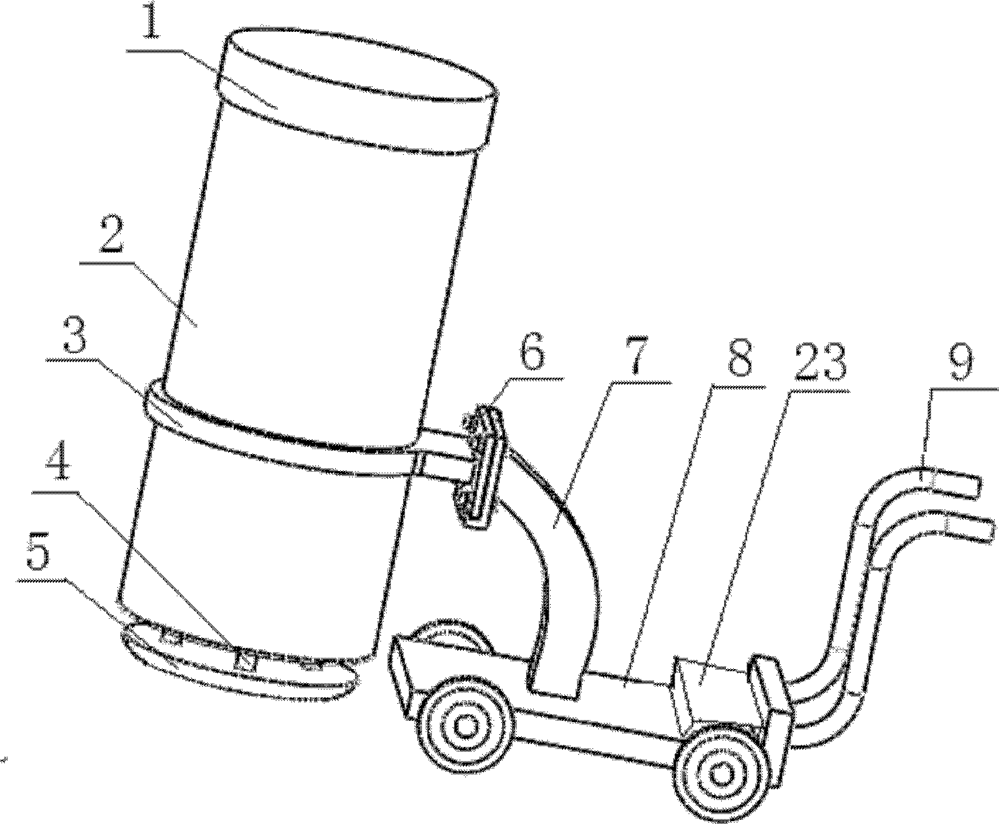
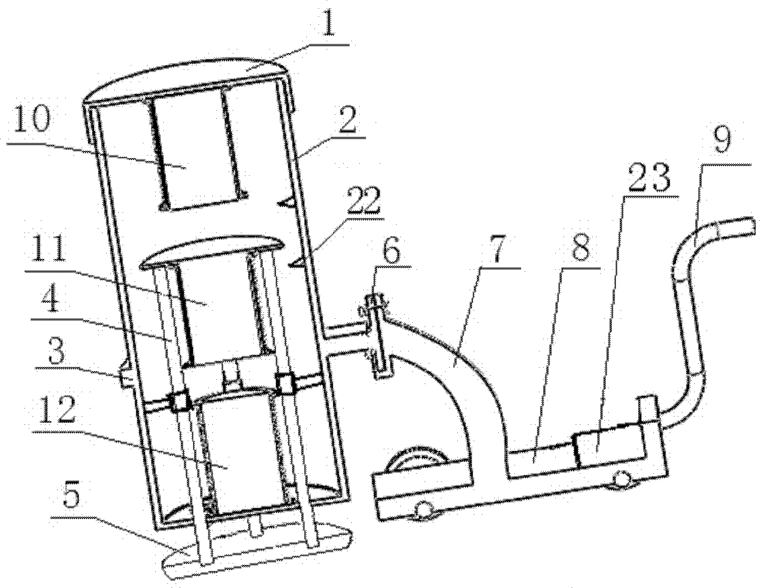
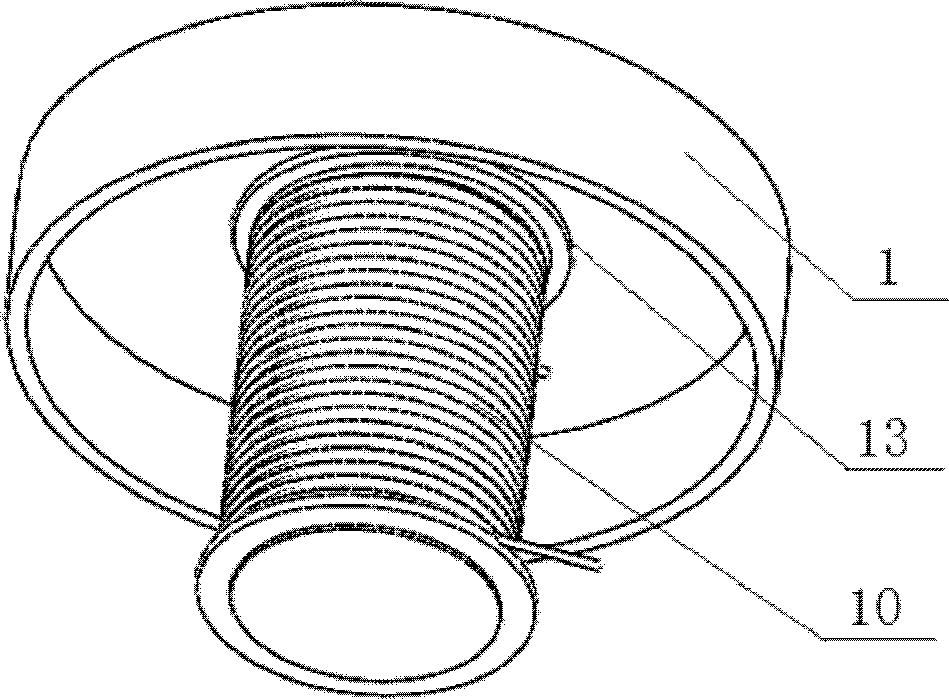
[0024] Embodiment 1: The structure of a kind of electromagnetic tamping machine of the present invention is as follows figure 1 , 2 As shown, it includes a casing, a pressure plate body, an electromagnet, a travel switch and a trolley. The casing is composed of a top cover 1 and a casing cylinder 2. The lower end of the casing casing is provided with a circular groove bottom; the inner wall of the casing casing Guide holes 14 are provided; the platen body is composed of a middle plate 17, a pressure head 5 and four pressure rods 4, and the four pressure rods 4 are connected to the middle plate 17 and the pressure head 5, and the pressure head is at the lowermost end of the pressure plate body ; The electromagnets described see figure 2 Consists of top electromagnet 10, middle electromagnet 11 and bottom electromagnet 12; top part assembly of the present invention sees image 3 , the top electromagnet is welded on the top annular groove 13 of the top cover 1; the bottom elec...

Embodiment 2

[0026] Embodiment 2: the assembly process of a kind of electromagnetic compactor of the present invention is:

[0027] (1) Electromagnet assembly: Assemble two electromagnets with a sleeve, iron core and coil, first wind the coil on the sleeve, and then insert the iron core into the sleeve with the coil, and the iron core and the sleeve have an interference fit , for the top electromagnet and the bottom electromagnet; then use a sleeve to wind the coil of the middle electromagnet, and the iron core is loaded into the sleeve of the middle electromagnet through interference fit; the bottom of the middle electromagnet is fixed on the tray with four bolts superior.

[0028](2) Assembling the housing cylinder: First, use an assembled bottom electromagnet to connect the circular bottom groove at the bottom of the housing cylinder by welding; then assemble the assembled middle electromagnet into the housing cylinder, and four pressing rods Connect along the four fixed guide holes 14...

Embodiment 3

[0034] Embodiment 3: The working process of the electromagnetic tamping machine of the present invention is: when the controller is not powered, the middle electromagnet is in the lower part of the casing due to gravity, and is in contact with the lower travel switch at this time. When the controller is powered on, the top electromagnet The upper part of the top electromagnet is S pole, and the lower part is N pole; the upper part of the bottom electromagnet is N pole, and the lower part is S pole; according to the signal from the travel switch, the controller will set the middle electromagnetic The iron supplies power, so that the upper part of the middle electromagnet is an S pole, and the lower part is an N pole. In this way, the top electromagnet will give the middle electromagnet a suction force, and the bottom electromagnet will give the middle electromagnet a repulsion force, prompting the middle electromagnet to go back. The current to the middle electromagnet is small ...


PUM


Abstract

The invention relates to an electromagnetic tamper, which comprises a housing, a plate pressing body, an electromagnet, a travel switch and a trolley, wherein the plate pressing body consists of four pressure bars connected with a middle flat panel and a pressure head, metal guide rails are arranged on the four pressure bars and can be used as wires for supplying power for a middle electromagnet; a top electromagnet is welded below a top cover and the middle electromagnet is arranged between the middle flat panel and a pallet; a bottom electromagnet is welded at the bottom of a housing tube; the travel switch is arranged on the internal wall of the housing tube and a hole is formed in the wall of the housing tube so that wires can be led out and connected to a power supply controller; and the housing tube is fixedly connected with a trolley through a connecting flange on a metal connecting sleeve. Direct current is applied to the top electromagnet and the bottom electromagnet and alternating square wave current is applied to the middle electromagnet. According to the invention, three electromagnets combined with the travel switch are used for the downward tamping action and the upward retracting action of the tamper based on the electromagnet principle that same electric charges mutually repulse and opposite electric charges attract. The electromagnetic tamper disclosed by the invention has the characteristics of a simple structure, easy control, good expansibility and capabilities of implementing the vibration tamping and impaction tamping function and adjusting the impaction frequency and the vibration amplitude.

Description

technical field [0001] The present invention relates to an electromagnetic compacting machine, specifically a principle of using electromagnets of the same sex to repel each other and opposite sexes to attract each other. Three electromagnets are used to complete the process of punching down and going up of the compacting machine, so as to realize the effects of vibration compaction and impact compaction. electromagnetic tamping machine. Background technique [0002] In recent years, my country's infrastructure construction has developed rapidly. However, a common problem at present is that the foundation collapses due to uneven force on the ground. One of the effective ways to solve this problem is to increase the compactness and bearing strength of the ground through compaction of special mechanical equipment, and reduce the post-construction settlement of the fill. At present, there are many traditional tamping equipment, but they are basically large and heavy machinery...

Claims


Application Information

Patent Timeline
Patent Type & Authority Patents(China)
IPC IPC(8): E02D3/046H01F7/06
Inventor 张伟民陈琪左国勇李亚锋张建辉张宁饶建华韩光超
Owner CHINA UNIV OF GEOSCIENCES (WUHAN)
Learn More