Hydraulic switch valve

A conversion valve and hydraulic technology, applied in the hydraulic field, can solve the problems of increasing the failure rate of valve core stuck, increasing the failure rate of hydraulic system, etc., and achieve the effect of avoiding conversion interference, improving dynamic performance and reducing failure rate

Active Publication Date: 2012-06-27
JINCHENG NANJING ELECTROMECHANICAL HYDRAULIC PRESSURE ENG RES CENT AVIATION IND OF CHINA
View PDF5 Cites 5 Cited by
  • Summary
  • Abstract
  • Description
  • Claims
  • Application Information

AI Technical Summary

Problems solved by technology

Due to the embedded structure of the double spool during state transition, the motion inertia between the spools will cause transient interference in the system, and the embedded structure spool increases the failure rate of the spool stuck and increases the hydraulic pressure. system failure rate

Method used


Image

  • Hydraulic switch valve
  • Hydraulic switch valve
  • Hydraulic switch valve

Examples


Embodiment Construction

[0013] In order to better illustrate the present invention, it will be described in detail below in conjunction with the accompanying drawings.

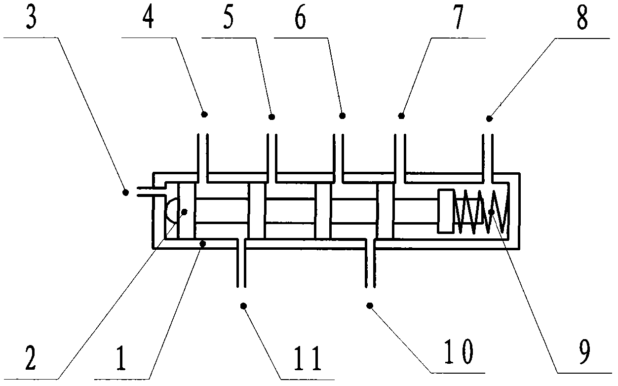
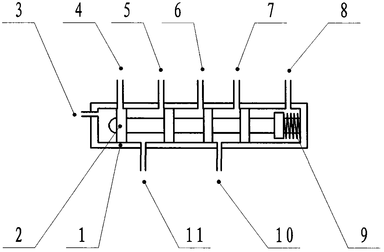
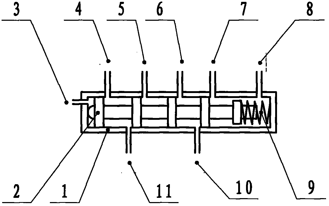
[0014] The hydraulic switching valve includes a switching valve core 1, a switching valve sleeve 2 and a spring 3. The switching valve sleeve is a hollow structure, and the side wall of the valve sleeve is provided with oil holes connected with the left and right cavities of the actuator and four servo control cavities and mechanical control cavities spaced apart from each other. At the same time, the switching valve sleeve is also provided with a control port for state switching and an oil return port for load relief, wherein the control port and the oil return port are located at both ends of the switching valve sleeve, and can be arranged on the side of the switching valve sleeve. end or side. Among them, the servo control cavity and the mechanical control cavity close to the control cavity are the left control channel, the servo...


PUM


Abstract

The invention belongs to the filed of hydraulic pressure and relates to a hydraulic switch valve. The hydraulic switch valve comprises a switch valve core, a switch valve sleeve and a spring, wherein the switch valve sleeve is of a hollow structure; oil holes communicated with a left cavity and a right cavity of an action cylinder, and four servo control cavities and mechanical operation cavities, are formed in the side wall of the valve sleeve; the four servo control cavities and mechanical operation cavities are mutually separated at intervals; a control opening used for state switching and an oil return opening used for unloading are also formed in the switch valve sleeve; the switch valve core is arranged in the switch valve sleeve and has more than four convex shoulders; the width of the convex shoulders is more than the diameter of the oil holes; the distance between two convex shoulders corresponds to that between two oil holes in the side wall of the switch valve sleeve; and one end of the spring is sleeved on the end head of the switch valve core, and the other end of the spring props against the inner wall of the switch valve sleeve. The convex shoulders of the valve core are used for operating the control cavities to switch operation states of a hydraulic part and distribute flow, so switch interference is avoided, and the operation force is reduced, and the failure rate of the hydraulic part caused when the valve core is locked can be reduced.

Description

technical field [0001] The invention belongs to the hydraulic field and relates to a hydraulic switching valve. Background technique [0002] The state conversion of hydraulic components is generally realized through the double spool structure of the main valve, and the double spool structure is composed of a valve sleeve and a spool embedded with a spool. Due to the embedded structure of the double spool during state transition, the motion inertia between the spools will cause transient interference in the system, and the embedded structure spool increases the failure rate of the spool stuck and increases the hydraulic pressure. The failure rate of the system. Contents of the invention [0003] The purpose of the present invention is to provide a hydraulic switching valve that can avoid switching interference, improve dynamic performance, and effectively avoid the failure of hydraulic components when a single valve core is stuck. [0004] The technical scheme of the pre...

Claims


Application Information

Patent Timeline
Patent Type & Authority Applications(China)
IPC IPC(8): F15B13/02
Inventor 余永平陈屹
Owner JINCHENG NANJING ELECTROMECHANICAL HYDRAULIC PRESSURE ENG RES CENT AVIATION IND OF CHINA
Why Eureka
Try Eureka