Method for locking magnetizing inrush current of transformer

A technology of excitation inrush current and transformer, which is applied to electrical components, emergency protection circuit devices, etc., and can solve problems such as differential protection misoperation

Active Publication Date: 2012-06-27
长园深瑞继保自动化有限公司
View PDF5 Cites 25 Cited by
  • Summary
  • Abstract
  • Description
  • Claims
  • Application Information

AI Technical Summary

Problems solved by technology

If only "AND" brake logic is used for braking, the differential protection may malfunction when it is air-dropped on a non-faulty transformer

Method used


Image

  • Method for locking magnetizing inrush current of transformer
  • Method for locking magnetizing inrush current of transformer
  • Method for locking magnetizing inrush current of transformer

Examples


Embodiment 1

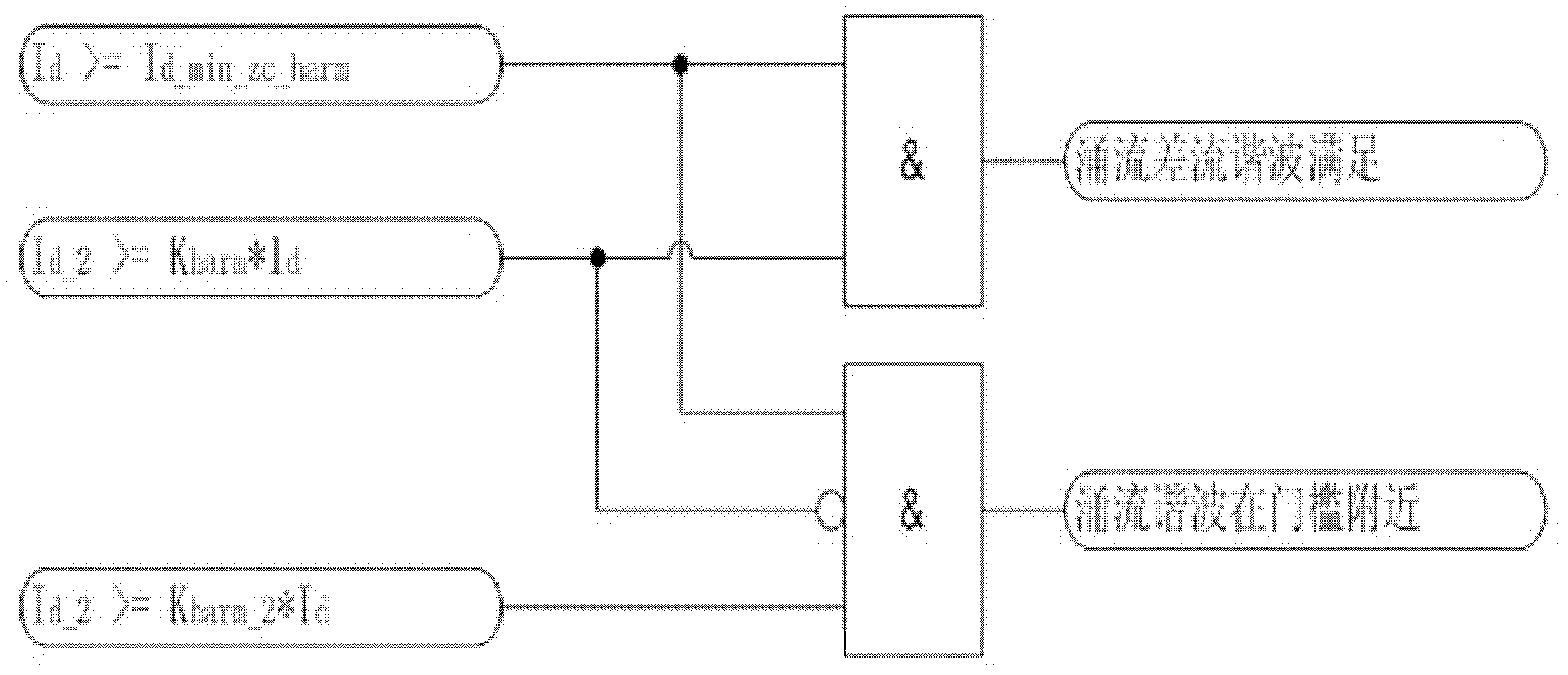
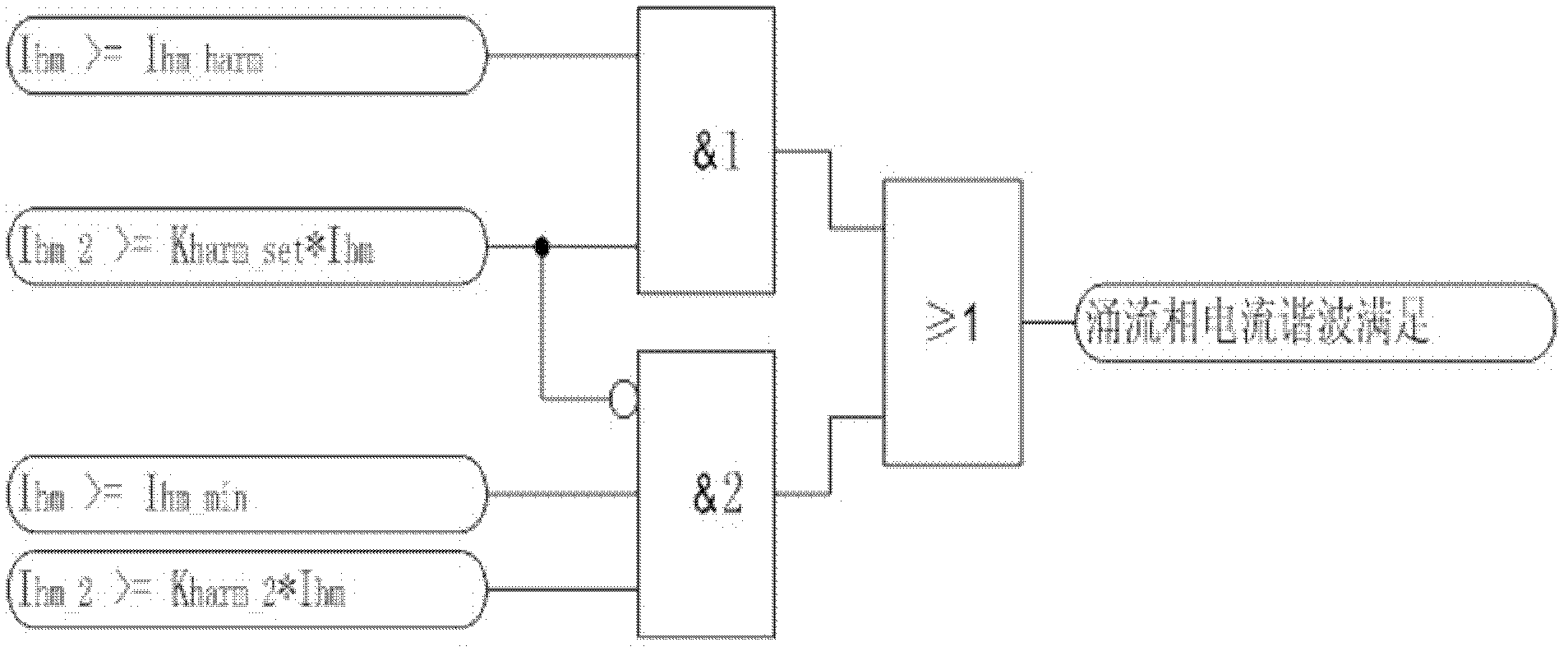
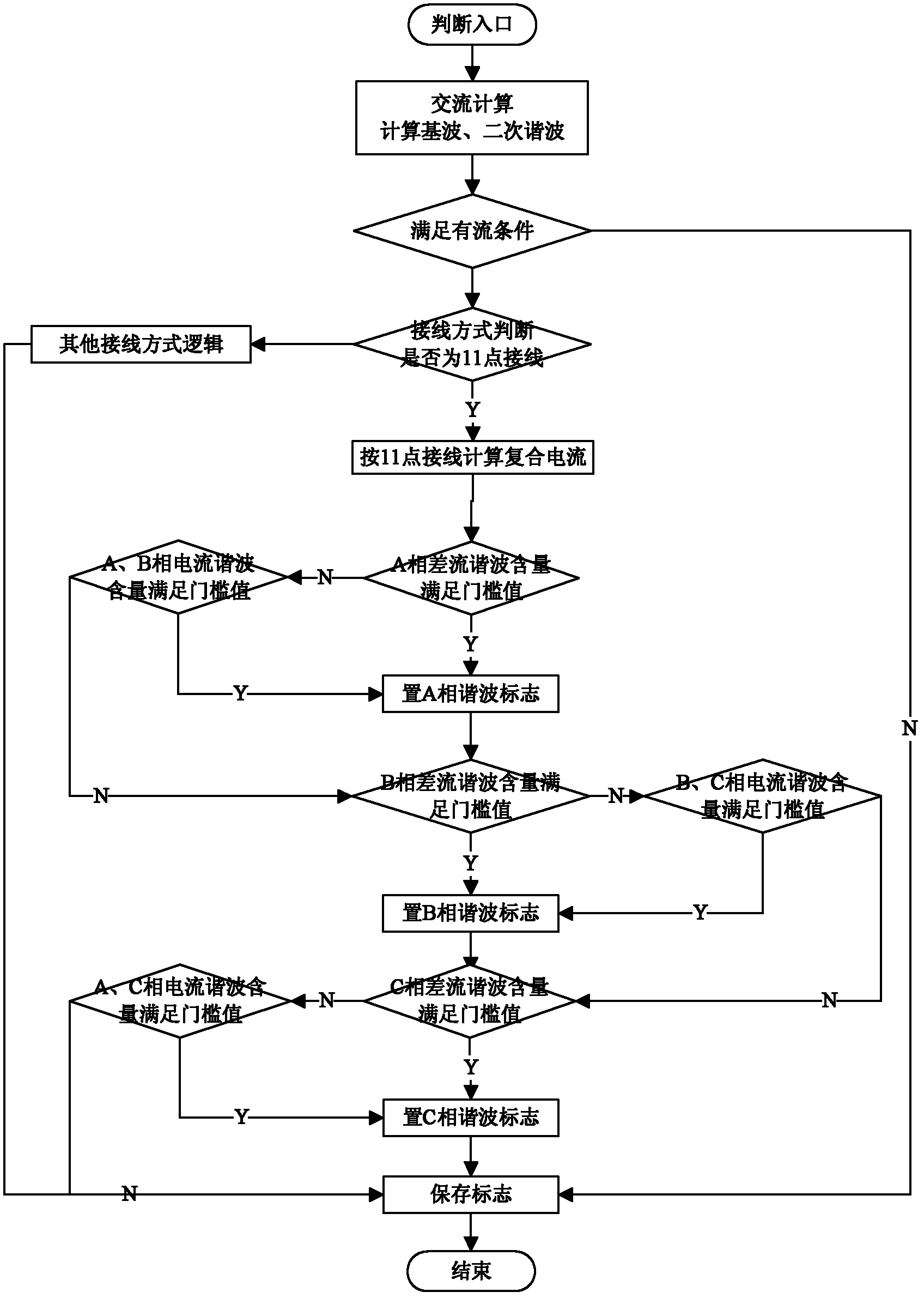
[0118] Example 1: Use or logic excitation inrush current can be effectively blocked during empty charging so that the protection does not operate. During the air-dropping process of the transformer, the phase currents of phase A and C on the high voltage side of the transformer contain more than 15% of harmonics, and the phase current of phase B contains less than 15% of harmonics. Using hybrid braking logic analysis: A, B, and C phases all contain differential currents, and the harmonics in the differential currents of phases A and C reach 15%, which does not meet the action conditions, and the harmonics in the differential currents of phase B do not reach 15%. Only phase B meets the operating conditions. At this time, the device adopts "or" logic for braking. When any phase differential excitation current inrush braking (both phases A and C meet the differential current inrush braking conditions), all three-phase ratios are blocked. Differential protection to reliably avoid ...

Embodiment 2

[0119] Embodiment 2: When the faulty transformer is empty-charged, the OR logic ratio differential protection can act quickly and sensitively. When the transformer is faulty and empty-charged, the phase currents of phase A and C on the high voltage side contain more than 15% of harmonics, and the phase current of phase B contains less than 15% of harmonics. Using hybrid braking logic analysis: A, B, and C three-phases all contain differential currents, and the harmonics in the differential currents of phase A reach 15%, which does not meet the operating conditions, and the harmonics in the differential currents of phases B and C do not reach 15%. And both phases meet the action conditions, reflecting the fault characteristics. At this time, the device adopts "AND" logic for braking, and when single-phase differential current inrush braking (all phase A meets the differential current inrush braking conditions), the phase ratio differential protection is blocked to reliably avoi...

Embodiment 3

[0120] Embodiment 3: In the process of empty charging, the logic excitation inrush current can be effectively blocked so that the protection does not operate. During the air-dropping process of the transformer, the phase currents of phase A and C on the high voltage side of the transformer contain more than 15% of harmonics, and the phase current of phase B contains less than 15% of harmonics. Using hybrid braking logic analysis: A, B, and C phases all contain differential currents, and the harmonics in the differential currents of phases A and C do not reach 15%, which satisfies the operating conditions, and the harmonics in the differential currents of phase B reach 15%, which is not satisfied Action condition, at this time, the device adopts "AND" logic for braking. When phase A meets the differential current excitation inrush braking condition, the A phase ratio differential is blocked, and when the C phase meets the differential current excitation inrush current braking co...


PUM


Abstract

The invention discloses a method for locking magnetizing inrush current of a transformer, aiming at realizing the technical effect that the magnetizing inrush current and internal faults are correctly recognized. The method disclosed by the invention comprises the following steps: a microcomputer relay device calculates amplitudes of fundamental waves and secondary harmonic waves of current alternating capacity at all the sides of the transformer, converts the current at the medium -voltage side and at the low-voltage side in the transformer into current at the high-voltage side in the transformer, calculates differential secondary harmonic waves at all the sides of the transformer, judges the differential harmonic waves at all the sides of the transformer and the phase current harmonic waves of all the phases as well as the magnetizing inrush current, and recognizes the magnetizing inrush current and internal faults so as to protect the transformer. Compared with the prior art, by judging the differential harmonic waves at all the sides of the transformer, the method is used for judging phase current harmonic waves of all phases at high-medium-voltage sides of the transformer, and judging the magnetizing inrush current characteristics and the fault characteristic during no-load switching in, so that the main transformer does not act by mistake in normal no-load switching on, the fault transformer is quickly removed when faults occurs in no-load switching on, further the characteristic of quick relay protection action is ensured, simultaneously the reliability for relay protection is improved and the safety of a power grid is protected.

Description

technical field [0001] The invention relates to a method for relay protection of an electric power system, in particular to a method for identifying excitation inrush current and fault current when airdropping a main transformer. Background technique [0002] When the transformer is in normal operation, there is an exciting inrush current only on the power supply side, which forms a part of the unbalanced current in the differential circuit through the current transformer. Under normal operating conditions, its value is very small, generally no more than 3% to 5% of the rated current of the transformer. When the transformer is powered on with no load or the voltage is restored after the external fault is removed, the magnetic flux in the transformer core increases sharply, the core is saturated instantly, and a large excitation inrush current with attenuation characteristics appears. The exciting inrush current will flow into the differential circuit through the current tra...

Claims


Application Information

Patent Timeline
Patent Type & Authority Applications(China)
IPC IPC(8): H02H7/045
Inventor 张广嘉许钰林石磊徐成斌
Owner 长园深瑞继保自动化有限公司
Why Eureka
Try Eureka