Sandwich permanent magnet synchronous motor rotor structure with solid-lamination axial direction compound

A permanent magnet synchronous, rotor structure technology, applied in the direction of magnetic circuit shape/style/structure, magnetic circuit rotating parts, etc., can solve the problem of low operating efficiency of solid rotor induction motor, poor starting performance of squirrel induction motor, permanent magnet synchronous motor Electric motors are expensive and other problems, to achieve obvious energy-saving effect, high cost performance, and small impact on the power grid

Inactive Publication Date: 2012-06-27
BEIJING JIAOTONG UNIV
View PDF6 Cites 8 Cited by
  • Summary
  • Abstract
  • Description
  • Claims
  • Application Information

AI Technical Summary

Problems solved by technology

[0004] The technical problem to be solved by the present invention is to overcome the poor starting performance of the cage induction motor, the low operating efficiency of the solid rotor induction motor and the high price of the permanent magnet synchronous motor

Method used


Image

  • Sandwich permanent magnet synchronous motor rotor structure with solid-lamination axial direction compound
  • Sandwich permanent magnet synchronous motor rotor structure with solid-lamination axial direction compound
  • Sandwich permanent magnet synchronous motor rotor structure with solid-lamination axial direction compound

Examples


Embodiment Construction

[0024] The present invention will be described in further detail below in conjunction with the accompanying drawings.

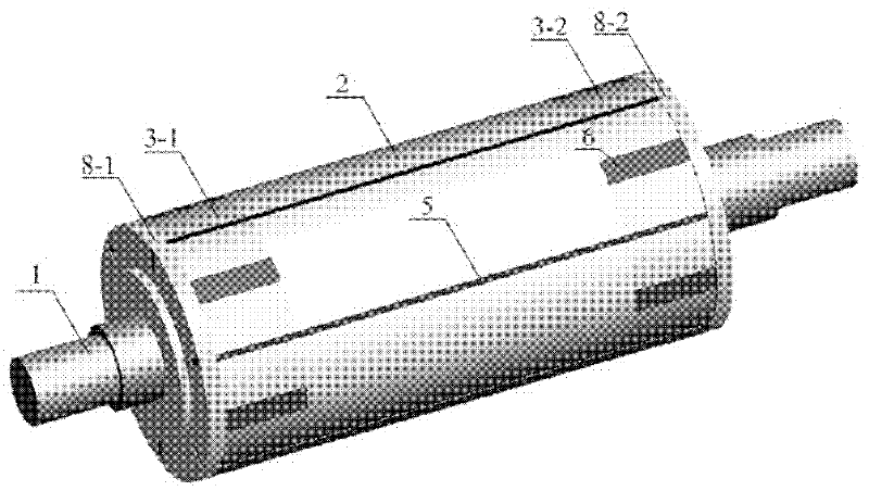
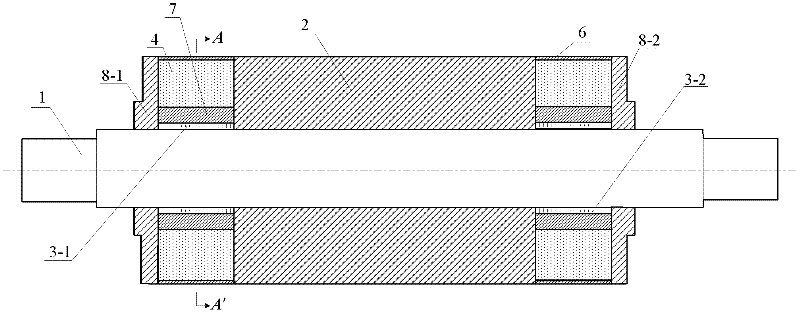
[0025] The rotor structure of the solid-lamination axial composite sandwich permanent magnet synchronous motor, such as figure 1 , 2 , 3. The rotor includes: rotor shaft 1, solid rotor part 2, left laminated rotor part 3-1, right laminated rotor part 3-2, first to Nth permanent magnet poles 4, first to Mth iron-copper alloy starter Cage bars 5, first to Nth aluminum bronze slot wedges 6, first to Nth aluminum spacer magnets 7, and left and right end protection covers 8-1, 8-2.

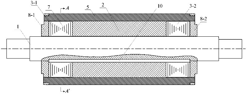
[0026] The left laminated rotor part 3-1, the solid rotor part 2 and the right laminated rotor part 3-2 are sequentially set on the rotor shaft 1, and are installed on the rotor shaft 1 through the key iron 10. The left laminated rotor part 3-1 and the right laminated rotor part 3-2 are completely symmetrical, such as image 3 .

[0027] The first to Nth aluminum spacer magnets 7...


PUM


Abstract

The invention provides a sandwich permanent magnet synchronous motor rotor structure with solid-lamination axial direction compound, belonging to the motor technology field. Problems that starting performance of a cage type induction motor is poor, operation efficiency of a solid rotor induction motor is low, and a price of a permanent magnet synchronous motor is expensive are solved. A left lamination rotor part, a solid rotor part and a right lamination rotor part of the rotor structure are sleeved on a rotor shaft in order and are installed on the rotor shaft through key iron. An aluminum magnetic isolation body and a permanent magnet pole are respectively placed in radial slots of the two lamination rotor parts. Aluminum bronze slot wedges are embedded in dovetail slots at openings of the radial slots of the two lamination rotor parts. Iron copper alloy starting cages are embedded in an axially through groove which is formed after installation of the left lamination rotor part, the solid rotor part and the right lamination rotor part. A left end protecting cover and a right end protecting cover are installed at outer side surfaces of the left lamination rotor part and the right lamination rotor part and are in cooperation fixation with rectangular terminals at two ends of the iron copper alloy starting cages through a respective rectangular aperture.

Description

technical field [0001] The invention relates to a rotor structure of a sandwich type permanent magnet synchronous motor, which belongs to the technical field of motors. Background technique [0002] The cage induction motor has the advantages of simple structure, reliable operation, high efficiency, easy manufacture, low cost, and durability, but there are also some disadvantages. One of the main problems is that the starting torque is not large and the overload capacity is not strong. This problem has not yet been satisfactorily resolved. For this reason, people have conducted in-depth research on solid rotor motors. Theoretical analysis and experimental results show that: when the solid rotor induction motor starts from a static state (slip s = 1) to a stable working state (slip is small) under a constant applied voltage, the rotor impedance automatically experiences a change from large to small. It is quite similar to the continuous and smooth reduction of the rotor sta...

Claims


Application Information

Patent Timeline
Patent Type & Authority Applications(China)
IPC IPC(8): H02K1/27
Inventor 曹君慈李伟力张晓晨霍菲阳张奕黄刘啸尘
Owner BEIJING JIAOTONG UNIV
Why Eureka
Try Eureka