Data transmission method and apparatus thereof
A data transmission method and data transmission technology, applied in the field of data transmission methods and devices, can solve the problems of not giving clear regulations and the like
- Summary
- Abstract
- Description
- Claims
- Application Information
AI Technical Summary
Problems solved by technology
Method used
Image
Examples
Embodiment 1
[0152] Embodiment 1: The available subframe is the subframe of the physical downlink control channel PDCCH. The PDCCH subframe is a DL subframe or DwPTs, and includes PDCCH or E-PDCCH or R-PDCCH.
[0153] For onDurationtimer, drx-InactivityTimer, drx-RetransmissionTimer, the length statistics can be in the following ways:
[0154] Method 1: Perform statistics according to the union or intersection of PDCCH subframes in all cells aggregated by the UE, without considering uplink / downlink collision subframes at all, or if the uplink / downlink collision subframes are used for DL data transmission, then the subframes are also It can be used as PDCCH subframe statistics.
[0155] Taking the union of PDCCH subframes of all cells aggregated according to UE as an example, it is first necessary to determine the PDCCH subframes of each cell. If the uplink / downlink collision subframe is not considered at all, then the PDCCH subframe on each cell is the downlink subframe or DwPTS subfra...
Embodiment 2
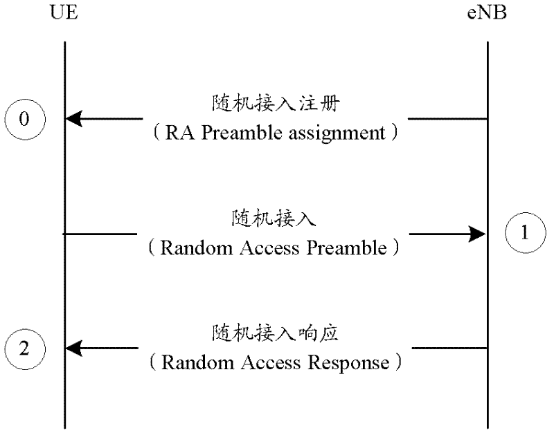
[0161] Embodiment 2: The available subframe is the available subframe of Msg1 in the non-contention random access process.
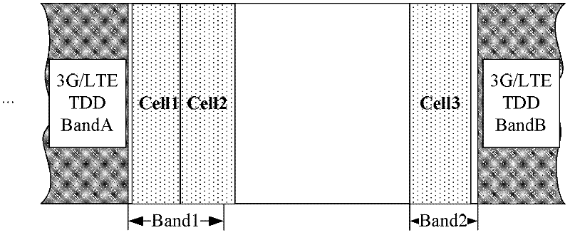
[0162] Assume that the user equipment first establishes an RRC connection with the base station on Cell2 (that is, Cell2 is a PCell). Due to the UL data transmission requirements, the base station needs to add an SCell (that is, Cell1) for the user equipment. Since the SCell and PCell are not in the same TAG, the base station needs to be on Cell2 Sending a PDCCH order (order) on Cell1 triggers random access on Cell1, assuming that the receiving time of PDCCH order on Cell2 is: radio frame number (SFN)=N, subframe number n=8, then the user equipment can meet the following two conditions Conditional uplink subframes send Msg1:
[0163] Condition 1: The subframe number satisfies: n+k 2 , where k 2 ≥6.
[0164] Condition 2: The uplink subframe on the cell sending the Msg1 is a non-uplink / downlink collision subframe or an uplink / downlink collision subframe...
Embodiment 3
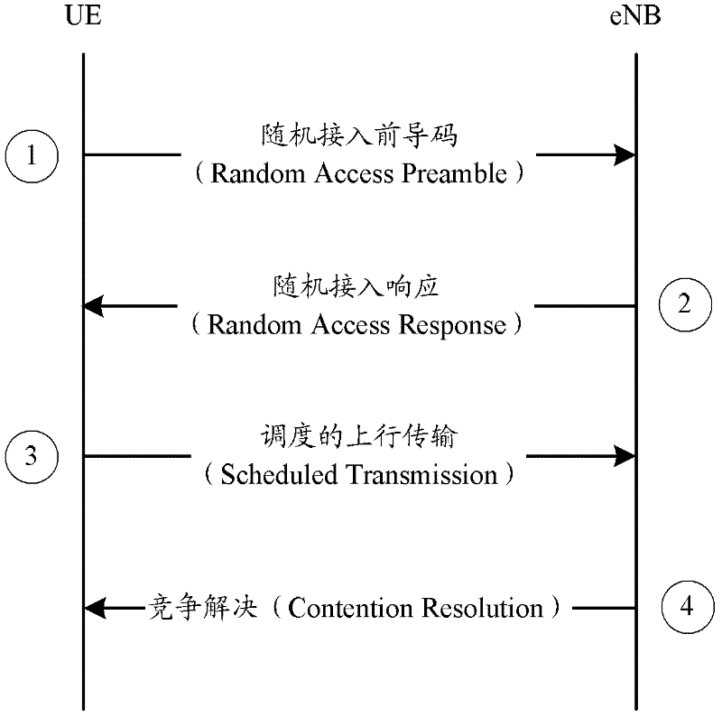
[0167] Embodiment 3: The available subframe is the available subframe of Msg3 in the contention random access process.
[0168] Assume that the user equipment first establishes an RRC connection with the base station on Cell2 (that is, Cell2 is a PCell). Due to the UL data transmission requirements, the base station needs to add an SCell (that is, Cell1) for the user equipment. Since the SCell and PCell are not in the same TAG, the base station needs to be on Cell2 Sending a PDCCH order on Cell1 triggers random access on Cell1, assuming that the moment when the user equipment receives Msg2 on Cell1 is: SFN=N, subframe number n=0.
[0169] Case 1: If the UL delay field is set to 0, then the user equipment can send Msg3 in the first uplink subframe that meets the following two conditions:
[0170] Condition 1: The subframe number satisfies: n+k 1 (k 1 ≥6).
[0171] Condition 2: The uplink subframe on the cell sending Msg3 is a non-uplink / downlink collision subframe or an upli...
PUM
 Abstract
Description
Claims
Application Information
 - R&D
- Intellectual Property
- Life Sciences
- Materials
- Tech Scout
- Unparalleled Data Quality
- Higher Quality Content
- 60% Fewer Hallucinations
Browse by: Latest US Patents, China's latest patents, Technical Efficacy Thesaurus, Application Domain, Technology Topic, Popular Technical Reports.
© 2025 PatSnap. All rights reserved.Legal|Privacy policy|Modern Slavery Act Transparency Statement|Sitemap|About US| Contact US: help@patsnap.com


