
Multi-purpose automatic comprehensive optometry equipment

An automatic comprehensive and multi-functional technology, which is applied in the fields of eye testing equipment, medical science, diagnosis, etc., can solve problems such as overcorrection or undercorrection, single function, small distance, etc., to improve measurement accuracy, avoid detection errors, and facilitate The effect of the operation

Inactive Publication Date: 2012-07-04
张仁发
View PDF7 Cites 12 Cited by
  • Summary
  • Abstract
  • Description
  • Claims
  • Application Information

AI Technical Summary

Problems solved by technology

The existing optometry has the following disadvantages: (1) the head position fixing device of the optometry only includes a forehead rest that can be movably connected to the optometry. It has a great impact on the measurement accuracy. Generally, the distance between the apex of the cornea and the test lens should be kept at about 11mm to 12mm. If the distance is too large or too small, it will cause over-correction or under-correction.
The existing head position fixing device cannot guarantee this test distance. The tester often puts his eyes close to the eye hole because he cannot see clearly, and the distance is too small, which may cause the lens to fog and affect the measurement accuracy.
(2) The optometry can only be tested with the horizontal visual axis. Normally, the human eye is used to studying or working. It is most comfortable to read with the eyeball down about 25-32 degrees. The optometry instrument should also meet the specific needs of the human eye, so as to reduce the detection error caused by the change of the visual axis direction of myopia. The existing optometry instrument cannot change the visual axis angle according to the needs.
(3) Most refractometers can only detect static vision and have a single function. There is no dynamic vision test function designed for workers in special industries such as pilots and high-speed train drivers who have been engaged in high-speed driving for a long time, and cannot meet the needs of these workers.

Method used


Image

  • Multi-purpose automatic comprehensive optometry equipment
  • Multi-purpose automatic comprehensive optometry equipment
  • Multi-purpose automatic comprehensive optometry equipment

Examples


Embodiment Construction

[0027] The present invention will be further described below through specific embodiments.

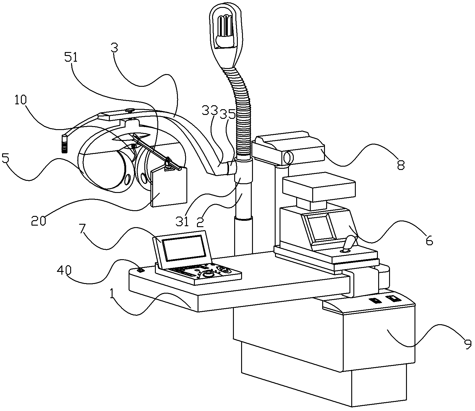
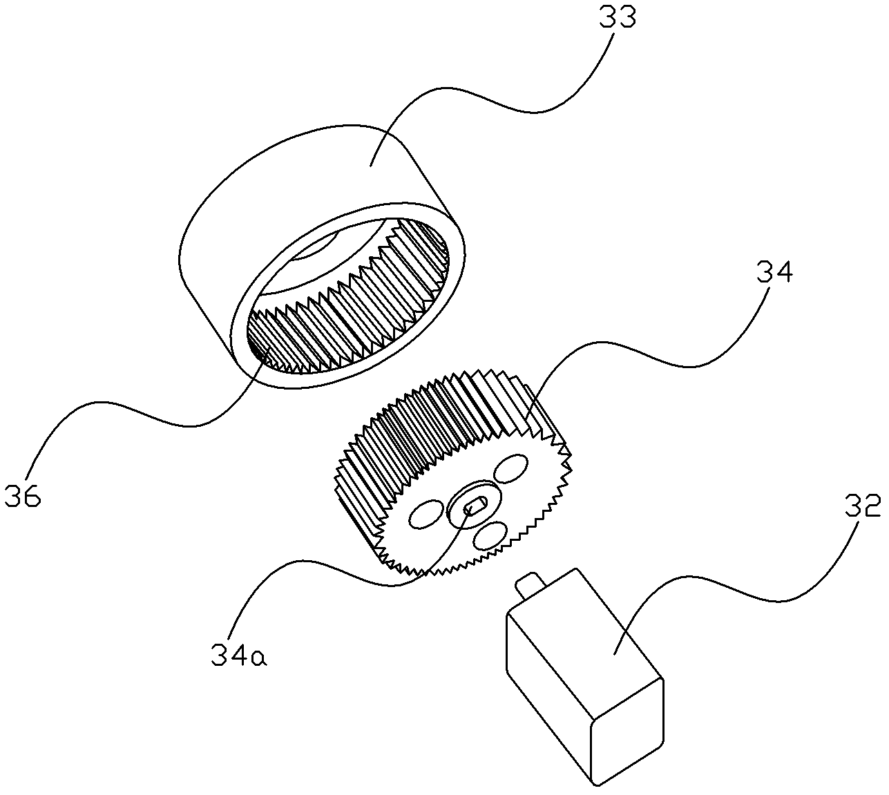
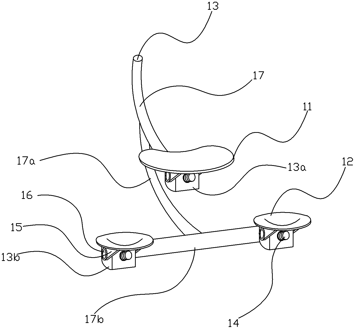
[0028] refer to figure 1 , figure 2 , a multifunctional automatic comprehensive optometry equipment, including a combination 1, a refractometer 5 supported above the combination platform 1 through a fixed rod 2 and a rotating arm 3, a computer optometry machine 6 slidingly arranged on the combination platform 1, and an operation control panel 7. The projector 8 and the power supply box 9, the power supply box 9 are connected with the optometry instrument 5, the computer optometry machine 6, the operation control panel 7 and the projector 8 respectively. The rotating arm 3 is rotatably connected to the fixed rod 2 by a horizontal rotating part 31, and the refractor 5 is fixed on the rotating arm 3 and is provided with a head position fixing device 10 (refer to image 3 ), between the rotating arm 3 and the horizontal rotating portion 31, there is also a longitudinal rotating portion ...


PUM


Abstract

The invention provides multi-purpose automatic comprehensive optometry equipment which comprises a combination table, an optometry instrument, a computer optometry machine, an operation control panel, a projector and a power box, wherein the power box is connected with the optometry instrument, the computer optometry machine, the operation control panel and the projector respectively; a rotation arm is rotatably connected on a fixing rod through a transverse rotation part; the optometry instrument is fixed on the rotation arm and is provided with a head fixing device; a longitudinal rotation part enabling the optometry instrument to rotate along the vertical direction is arranged between the rotation arm and the transverse rotation part; the head fixing device comprises a forehead support and a cheekbone position support which is arranged below the forehead support, wherein the forehead support and the cheekbone position support are symmetrically arranged. With the adoption of the equipment, the optometry instrument can rotate along the vertical direction, and the cheekbone position support is additionally arranged on the head fixing dice, so that certain distances can be kept among head positions of testers, and the detection precision is improved.

Description

technical field [0001] The invention relates to vision detection equipment, in particular to a multifunctional automatic comprehensive optometry equipment. Background technique [0002] The principle of optometry is to check the concentration of light after it enters the eyeball, and to measure the difference in vergence between the tested eye and the emmetropic eye based on the state of the emmetropic eye. As one of the optometry instruments, the comprehensive optometry instrument is produced according to the above optometry principle. The lens or cylinder is put into the wheel system, and the lens can be changed more effectively and quickly through a simple knob to achieve the optometry. Purpose; at the same time, the lens inside the optometry instrument is in a closed state and is not easy to get dirty. The comprehensive optometry instrument is generally composed of three parts: a strength tester, a projector, and an optometry combination table. Most of them use a rotati...

Claims


Application Information

Patent Timeline
Patent Type & Authority Applications(China)
IPC IPC(8): A61B3/036
Inventor 张仁发
Owner 张仁发
Learn More