Supercharge Your Innovation With Domain-Expert AI Agents!

Selective catalytic reduction device for flue gas denitrification and application method thereof

A selective, flue gas technology, applied in chemical instruments and methods, separation methods, dispersed particle separation, etc., can solve the problems of catalyst clogging, catalyst poisoning, etc., reduce manufacturing costs, increase market share, and facilitate manufacturing Effect

Inactive Publication Date: 2013-12-11
SHANGHAI UNIVERSITY OF ELECTRIC POWER
View PDF14 Cites 0 Cited by
  • Summary
  • Abstract
  • Description
  • Claims
  • Application Information

AI Technical Summary

Problems solved by technology

[0013] The purpose of the present invention is to provide a selective catalytic reduction flue gas with catalyst / fly ash separation function in order to solve the above-mentioned technical problems such as catalyst clogging and catalyst poisoning in the existing selective catalytic reduction (SCR) flue gas denitrification process. The denitrification device is to install a catalyst / fly ash separation device, and the catalyst is in the form of particles, which are spread on the porous bed of the catalyst / fly ash separation device with a certain slope, and the air is blown back. The fly ash remaining on the catalyst is regularly purged out to improve the flow characteristics of the catalyst layer. At the same time, when the performance of the catalyst deteriorates due to long-term operation, the catalyst is activated and supplemented with the activated catalyst to stabilize the catalyst layer against the flue gas. NOx removal effect

Method used


Image

  • Selective catalytic reduction device for flue gas denitrification and application method thereof
  • Selective catalytic reduction device for flue gas denitrification and application method thereof

Examples


Embodiment 1

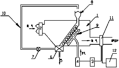
[0050] A selective catalytic reduction flue gas denitrification device, its structure schematic diagram is as follows figure 1 As shown, 1 is the NOx removal device, 2 is the NOx content detector, 3 is the electrical sensor for NOx concentration detection, 4 is the ventilation device, 5 is the fly ash discharge port, 6 is the catalyst / fly ash separation device, and 7 is the Catalyst regeneration instrument, 8 is the catalyst adding funnel, 9 is the ventilation plate, 10 is the catalyst delivery pipe, 11 is the automatic valve, 12 is the upper computer, 13 is the porous bed layer for laying the catalyst;

[0051] The ventilation plate 9 is placed under the porous bed 13 of the catalyst, and the ventilation plate 9 and the porous bed 13 of the catalyst are installed in the NOx removal device and are at a 30° angle to the horizontal direction of the NOx removal device 1. o ~45 o The included angle; ventilation plate 9 and the porous bed layer 13 interface schematic diagram of la...


PUM


Abstract

The invention discloses a selective catalytic reduction device for flue gas denitrification. The selective catalytic reduction device for flue gas denitrification comprises an NOx content detecting instrument, an NOx concentration detecting electrical sensor, a catalyst-paving porous bed and a catalyst / fly ash separating device and also comprises an NOx removing device, a ventilating device, a ventilating plate, a catalyst regenerating instrument, a catalyst hopper and a catalyst conveying pipeline. A catalyst can be recycled when the fly ash is removed; air is inflated into the selective catalytic reduction device for the flue gas denitrification along a certain angle to blow off the fly ash falling on the catalyst, so that the problems that the catalyst cannot work normally due to poisoning caused by fly ash mixing and the increase of flow resistance of a catalyst layer can be solved; the NOx content detecting instrument can detect the concentration of NOx in flue gas denitrified by the selective catalytic reduction device in real time, and is connected with a ventilating port through the NOx concentration detecting electrical sensor; and when the NOx content is higher than a certain value, the ventilating port automatically ventilates to blow the fly ash, and when the NOx content is lower than a certain value, the ventilating port automatically closes, so that the automatism can be realized.

Description

technical field [0001] The invention relates to a selective catalytic reduction flue gas denitrification device with simple operation, small occupied space, convenient control, high reliability and good economy and its application technology in the denitrification process. Background technique [0002] With the enhancement of environmental protection awareness, the air pollution caused by NOx emissions from thermal power plants has increasingly attracted the attention and attention of various countries. On July 29, 2011, the latest version of " The Emission Standard of Air Pollutants for Thermal Power Plants (GB13223-2011) puts forward extremely strict restrictions on NOx emissions from thermal power plants. To meet the new emission standards, low-nitrogen combustion technology alone cannot be achieved, and flue gas denitrification measures must be carried out. Currently, thermal power plants mainly use selective catalytic reduction (SCR) flue gas denitrification devices. T...

Claims


Application Information

Patent Timeline
Patent Type & Authority Patents(China)
IPC IPC(8): B01D53/90B01D53/56
Inventor 吴江任建兴潘卫国何平孟帅琦石宙郭腾孙嘉奎
Owner SHANGHAI UNIVERSITY OF ELECTRIC POWER
Features
  • R&D
  • Intellectual Property
  • Life Sciences
  • Materials
  • Tech Scout
  • Unparalleled Data Quality
  • Higher Quality Content
  • 60% Fewer Hallucinations
Learn More