
Rotating cutting tool and guide insert therefor

A technology of cutting tools and cutting inserts, applied in the direction of manufacturing tools, drill accessories, components of boring machines/drilling machines, etc., can solve problems such as damage to the surface, and achieve the effect of avoiding impaction

Active Publication Date: 2012-07-04
KENNAMETAL INC
View PDF7 Cites 7 Cited by
  • Summary
  • Abstract
  • Description
  • Claims
  • Application Information

AI Technical Summary

Problems solved by technology

[0005] However, it has been found that due to such a deeply set screw head, drilling chips can get stuck in the area of ​​the screw head and thus tend to scrape along the inner wall of the borehole and damage its surface

Method used


Image

  • Rotating cutting tool and guide insert therefor
  • Rotating cutting tool and guide insert therefor
  • Rotating cutting tool and guide insert therefor

Examples


Embodiment Construction

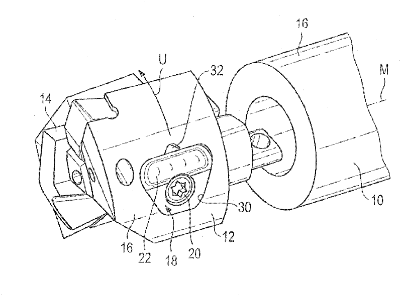
[0033] exist figure 1 A rotary cutting tool in the form of a drill is shown in . The cutting tool has a multi-piece support part with a shank 10 and a drill tip 12 fastened at the end face of the shank.

[0034] A plurality of interchangeable cutting inserts 14 (one of them is shown) are fastened on the end face of the support part (here the drill tip 12).

[0035] This two-piece support part with the shank 10 and the drill tip 12 has a peripheral wall 16, and for the sake of simplicity, the same reference numerals are used for the peripheral wall of the drill tip 12 and the shank 10 in this exemplary embodiment. circumference wall.

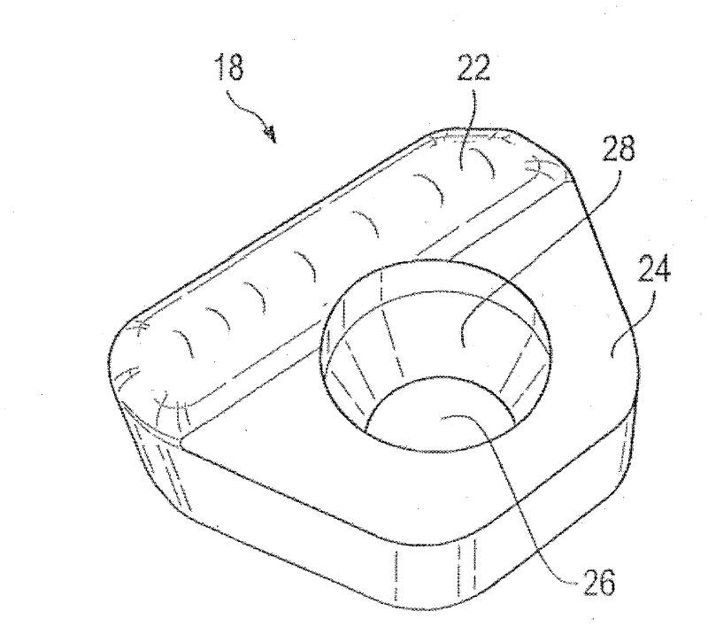
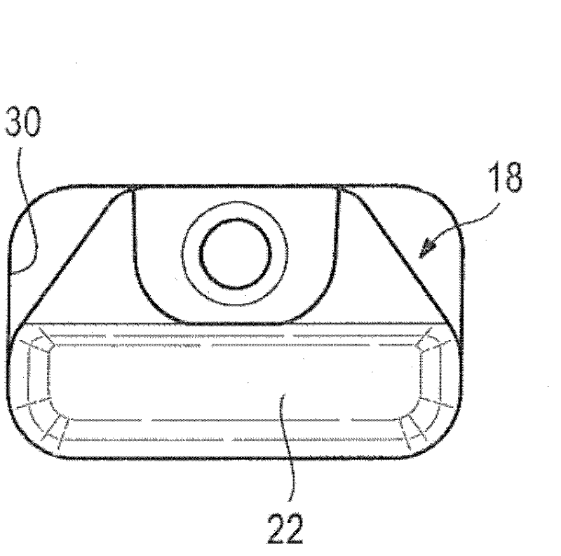
[0036] Near the free end of the support part in the present exemplary embodiment, in the drill bit 12 , guide inserts 18 without cutting edges and evenly distributed over the circumference are attached to the circumference by means of retaining means 20 on wall 16.

[0037]However, the invention is not limited to the embodiment shown, in whic...


PUM


Abstract

A rotating cutting tool includes a single or multi-piece support part which has a cutting insert (14) fastened thereto and at least one guide insert (18) disposed on a circumferential wall (16). The at least one guide insert (18) has a plurality of guide sections (22) protruding furthest radially. A holding device (20) is at the height of the guide sections (22) axially and is offset from the guide sections circumferentially. The invention also provides the corresponding guide insert.

Description

technical field [0001] The invention relates to a rotary cutting tool comprising a one-piece or multi-piece support part having an end face and a peripheral wall on which at least one preferably interchangeable cutting insert is provided and in which At least one interchangeable guide insert is fastened to the circumferential wall by a separate retaining device, the guide insert having no cutting edge and protruding radially relative to the circumferential wall, wherein the guide insert has The radially outwardly protruding one guide section. [0002] Such a rotary cutting tool is usually a drilling tool having a shank forming the support part or a shank together with the drill bit forming the support part for the interchangeable cutting insert. Rotary cutting tools can penetrate deeply into the workpiece, wherein it must be ensured that the cutting tool remains sufficiently stable and neither bends nor wobbles, taking into account its free projection length. Background tec...

Claims


Application Information

Patent Timeline
Patent Type & Authority Applications(China)
IPC IPC(8): B23B51/00B23B51/04
CPCB23B2251/56B23B51/0493Y10T408/45Y10T408/5586
Inventor H·M·耶格尔X·F·施皮歇廷格
Owner KENNAMETAL INC
Learn More