Full-automatic visual spot-welding robot

An automatic spot welding and fully automatic technology, applied in welding equipment, auxiliary welding equipment, welding/cutting auxiliary equipment, etc. problems, to achieve the effect of reducing product defects, excellent sports performance, and reducing errors

Active Publication Date: 2012-07-04
CHANGZHOU MINGSEAL ROBOT TECH CO LTD
View PDF6 Cites 14 Cited by
  • Summary
  • Abstract
  • Description
  • Claims
  • Application Information

AI Technical Summary

Problems solved by technology

[0002] At present, in the electro-acoustic industry, the welding of pads and enameled wires is done manually, such as foot-operated spot welding machines. Each time the position of the welding spot must be visually inspected, and the spot welding operation must be completed manually, which requires several parts of the body to work simultaneously. Concentrate on the completion, and the coordination requirements for workers are relatively high; because most of the workpiece pads and enameled wires are relatively thin, the manual welding error is relatively large, the work efficiency is very low, and the force of each welding is not easy to determine, and it is difficult to operate for a long time. The patient is prone to fatigue, which not only does not guarantee the quality of work, but also causes great damage to the eyes.

Method used


Image

  • Full-automatic visual spot-welding robot
  • Full-automatic visual spot-welding robot
  • Full-automatic visual spot-welding robot

Examples


Embodiment Construction

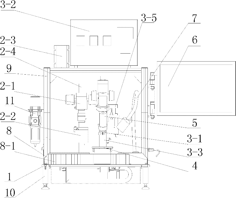
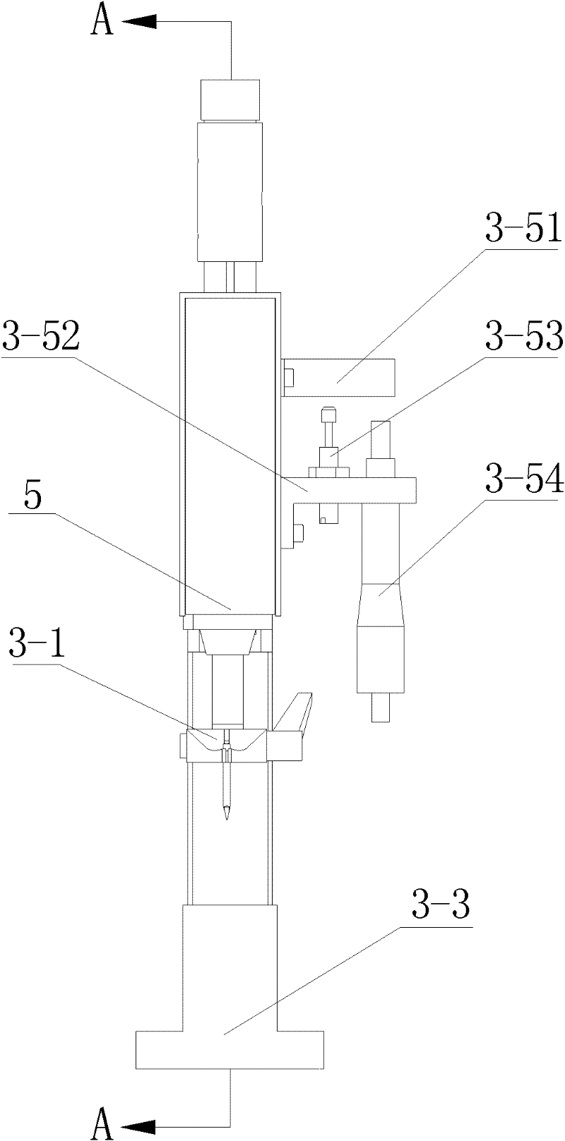
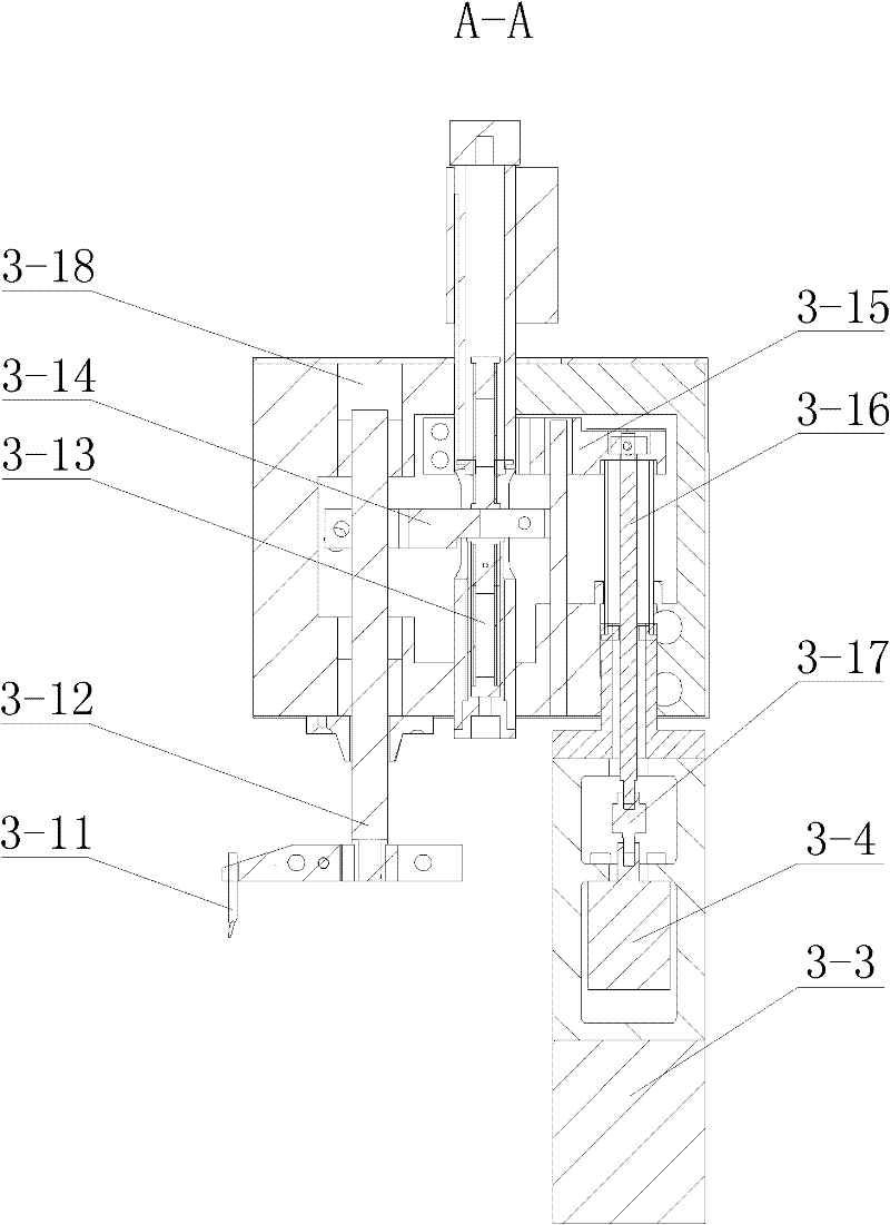
[0020] like Figure 1-Figure 3 A kind of fully automatic visual spot welding robot shown, comprises base plate mechanism 1, visual identification system, automatic spot welding system, two-dimensional motion platform system and is used for setting the industrial computer of visual parameter and data processing, described visual identification system, The automatic spot welding system, the motion platform system and the industrial computer are all arranged on the bottom plate mechanism 1 .

[0021] The visual recognition system includes an industrial camera 2-1, a light source 2-2 and a light source controller 2-3 for switching the light source 2-2 and adjusting the light intensity of the light source 2-2. The industrial camera 2-1 and the light source 2 -2 is connected to the bottom plate mechanism 1 through a lifting platform, the lifting platform is composed of a column 2-4 and two sliders arranged on the column 2-4, and the column 2-4 is fixedly connected to the bottom plat...


PUM


Abstract

The invention relates to a full-automatic visual spot-welding robot which comprises a bottom plate mechanism, as well as a visual identification system, an automatic spot-welding system, a motion platform system and an industrial personal computer (IPC) which are arranged on the bottom plate mechanism, wherein the visual identification system comprises an industrial camera, a light source and a light source controller; the industrial camera and the light source are connected with the bottom plate mechanism by virtue of a lifting table, and the light source is positioned under the industrial camera; the automatic spot-welding system comprises a micro-spot-welding mechanism and a micro-spot-welding controller; the micro-spot-welding mechanism is connected with the bottom plate mechanism by virtue of a lifting mechanism; the motion platform system comprises an X-axis module and a Y-axis module; the Y-axis module is slidably connected to the X-axis module; and the motion platform system is positioned below the visual identification system and the micro-spot-welding mechanism. The robot capable of realizing a full-automatic spot-welding function has the functions of automatically locating the spot-welding position of a workpiece in a visual way, guaranteeing the precise translational motion of the workpiece, welding in an automatic micro-spot-welding way, and the like.

Description

technical field [0001] The invention relates to a fully automatic visual spot welding robot, which is suitable for automatic spot welding of small copper wires and pads. Background technique [0002] At present, in the electro-acoustic industry, the welding of pads and enameled wires is done manually, such as foot-operated spot welding machines. Each time the position of the welding spot must be visually inspected, and the spot welding operation must be completed manually, which requires several parts of the body to work simultaneously. Concentrate on the completion, and the coordination requirements for workers are relatively high; because most of the workpiece pads and enameled wires are relatively thin, the manual welding error is relatively large, the work efficiency is very low, and the force of each welding is not easy to determine, and it is difficult to operate for a long time. The patient is prone to fatigue, which not only does not guarantee the quality of work, bu...

Claims


Application Information

Patent Timeline
Patent Type & Authority Applications(China)
IPC IPC(8): B23K37/00
Inventor 李长峰曲东升张逢靖徐庆海
Owner CHANGZHOU MINGSEAL ROBOT TECH CO LTD
Why Eureka
Try Eureka