Automatic tool changing device of high-speed machining center

A machining center and automatic tool changing technology, applied in positioning devices, metal processing equipment, metal processing machinery parts, etc., can solve problems such as maintenance costs that cannot be ignored, high prices, and difficult processing of cambered indexing cams, and achieve structural Simple, fast tool change, easy to create effects

Inactive Publication Date: 2014-06-11
HUBEI UNIV OF AUTOMOTIVE TECH
View PDF6 Cites 3 Cited by
  • Summary
  • Abstract
  • Description
  • Claims
  • Application Information

AI Technical Summary

Problems solved by technology

In addition, the arc surface indexing cam is difficult to process, the price is expensive, and the subsequent maintenance costs cannot be ignored

Method used


Image

  • Automatic tool changing device of high-speed machining center
  • Automatic tool changing device of high-speed machining center
  • Automatic tool changing device of high-speed machining center

Examples


Embodiment Construction

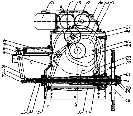
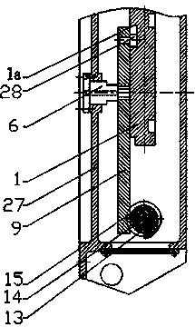
[0022] like figure 1 The automatic tool changing device of the high-speed machining center shown includes a box body 27, a tool arm spindle 13, a tool changing arm 18, a power transmission mechanism, a tool inserting mechanism, a tool changing mechanism, a tool locking mechanism, a transmission clutch mechanism, and a tool The arm main shaft 13 is supported on the casing 27 by a bearing, the knife arm main shaft can reciprocate axially, and the tool changing arm 18 is fixed on the front end of the knife arm main shaft 13 .

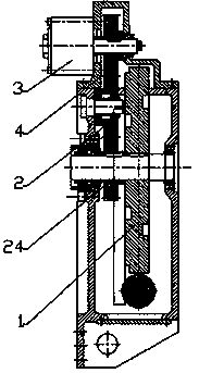
[0023] powertrain such as figure 1 , 2 As shown, the motor 5 is connected to the reducer 3, and the reducer is transmitted to the compound cam 1 through the gears 4, 2, 24. The compound cam is supported on the box through the rotating shaft. The axis of the compound cam is perpendicular to the axis of the tool changer arm. The compound cam It is composed of three contour curves 1a, 1b, 1c with different functions, which respectively control the mechanism...


PUM


Abstract

The invention provides an automatic tool changing device of a high-speed machining center, which aims to replace a tool position changing mechanism adopting an arc-surface indexing cam as a main body and has the advantages of simple structure and convenience in manufacture. The automatic tool changing device of the high-speed machining center comprises a box, a tool arm spindle, a tool changing arm, a power transmission mechanism, a tool plugging and unplugging mechanism, a tool position changing mechanism, a tool locking mechanism and a transmission clutch mechanism. The automatic tool changing device is particularly improved by the tool position changing mechanism and the transmission clutch mechanism, the tool position changing mechanism is provided with a rack mechanism meshed with a transmission gear hollowly sleeved on the tool arm spindle, the rack mechanism is in motion association with a composite cam by a position changing oscillating bar, the transmission clutch mechanism is structurally provided with a shaft sleeve hollowly sleeved on the tool arm spindle, one side of the shaft sleeve is fixedly connected with a transmission gear, a T-shaped groove is machined in the middle of a push rod of the tool locking mechanism, a certain angle is formed between the bottom of the T-shaped groove and the axis of the push rod, a T-shaped pin is mounted in the T-shaped groove and is inserted in a positioning hole of the tool arm spindle, and an axial groove matching with a journal of the T-shaped pin is disposed on the shaft sleeve.

Description

technical field [0001] The invention belongs to an automatic tool changing device, which is applied to a high-speed machining center to realize mutual exchange of tools on the main shaft of the machining center and a tool magazine, and relates to an automatic tool changing device and a method. Background technique [0002] The automatic tool changer of the high-speed machining center is an important functional part of the high-speed machining center. Its main function is to reduce the non-cutting time during the machining process and the error caused by multiple clamping workpieces, so as to improve production efficiency, reduce production costs, and improve machine tools. And even the production efficiency of the whole production line. In the current mainstream automatic tool changer for high-speed machining centers, the tool change is mainly realized by the arc indexing cam, which is the key component part. Compared with the mature technology abroad, there are still some ...

Claims


Application Information

Patent Timeline
Patent Type & Authority Patents(China)
IPC IPC(8): B23Q3/155
Inventor 邱新桥杨威
Owner HUBEI UNIV OF AUTOMOTIVE TECH
Why Eureka
Try Eureka