
End surface milling and multi-position end surface drilling and tapping compound machine tool

A face milling and compound machine tool technology, applied in the field of machine tools, can solve the problems of low processing efficiency, poor equipment rigidity, unsuitable for large size and large cutting allowance, etc., to achieve fast tool changing speed, strong equipment rigidity, clamping The effect of automatic adjustment of the holding position

Inactive Publication Date: 2019-08-16
SHANDONG YOT MACHINE TOOL MFG
View PDF0 Cites 3 Cited by
  • Summary
  • Abstract
  • Description
  • Claims
  • Application Information

AI Technical Summary

Problems solved by technology

[0003] The existing horizontal machining center or boring machine has low processing efficiency and poor equipment rigidity, so it is not suitable for processing with large size and large cutting allowance

Method used


Image

  • End surface milling and multi-position end surface drilling and tapping compound machine tool

Examples


Embodiment 1

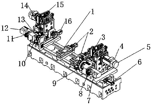
[0021] refer to figure 1 , an end face milling, multi-position end face drilling, and tapping compound machine tool in an embodiment of the present invention, including a bed 1 and a servo control system, the bed 1 is provided with guide rails, and fixtures are symmetrically provided on the guide rails System 2, a processing mechanism with symmetrical left and right ends of the guide rail. The processing mechanism includes a sliding seat. It is characterized in that a first feeding mechanism and a second feeding mechanism are respectively arranged on the two sliding seats. The first feeding mechanism The left power turret 10 and the right power turret 9 are respectively arranged on the feed mechanism and the second feed mechanism, and the first powerful milling power motor 14 and the second power motor 14 are respectively installed on the first feed mechanism and the second feed mechanism. Powerful milling power motor 5, cutter is all installed on the first powerful milling po...

Embodiment 2

[0025] On the basis of the first embodiment, the servo control system is composed of two channels or two systems, which realize simultaneous processing on both sides without interfering with each other, and can realize the left and right double linkage function.


PUM


Abstract

The invention relates to the technical field of machine tools, in particular to an end surface milling and multi-position end surface drilling and tapping compound machine tool. The end surface milling and multi-position end surface drilling and tapping compound machine tool comprises a machine tool body and a servo control system. A guide rail is arranged on the machine tool body, clamp systems are symmetrically arranged on the guide rail, processing mechanisms are symmetrically arranged at the left and right ends of the guide rail, each processing mechanism comprises a slide, a first feedingmechanism and a second feeding mechanism are separately arranged on the slides, a left power tool turret and a right power tool turret are respectively arranged on the first feeding mechanism and thesecond feeding mechanism, a first powerful milling power motor and a second powerful milling power motor are also respectively mounted on the first feeding mechanism and the second feeding mechanism,and tools are mounted on the first powerful milling power motor and the second powerful milling power motor. According to the structural arrangement of the device, the end surface milling and multi-position end surface drilling and tapping compound machine tool carries out processing at two ends simultaneously, so that the production efficiency of the end surface milling and multi-position end surface drilling and tapping compound machine tool is higher than that of a horizontal processing center or a boring mill. The end surface milling and multi-position end surface drilling and tapping compound machine tool is high in rigidity, has an independent end surface milling system and is suitable for processing with a relatively large dimension and a relatively large chipping allowance.

Description

technical field [0001] The invention relates to the technical field of machine tools, in particular to a compound machine tool for face milling, multi-position face drilling and tapping. Background technique [0002] A machine tool refers to a machine that manufactures a machine, also known as a machine tool or a tool machine, and is customarily referred to as a machine tool. Generally divided into metal cutting machine tools, forging machine tools and woodworking machine tools. There are many ways to process mechanical parts in modern machinery manufacturing: in addition to cutting, there are also casting, forging, welding, stamping, extrusion, etc. The final machining is done by cutting on the machine tool. Machine tools play an important role in the modernization of the national economy. [0003] The existing horizontal machining center or boring machine has low processing efficiency and poor equipment rigidity, and is not suitable for processing with large size and la...

Claims


Application Information

Patent Timeline
Patent Type & Authority Applications(China)
IPC IPC(8): B23P23/02
CPCB23P23/02
Inventor 蔡海波
Owner SHANDONG YOT MACHINE TOOL MFG
Learn More