
Integrated chained tool magazine capable of automatically picking up and replacing tools

A self-pickup tool change, chain tool magazine technology, applied in the field of integrated chain tool magazine, can solve problems such as unfavorable machine tool production line layout, influence of machine tool accuracy retention, occupation of machine tool side space, etc. Optimized design, avoids knife sleeve throwing out, and takes up less space

Pending Publication Date: 2020-08-28
北京精雕精密机械制造有限公司
View PDF0 Cites 2 Cited by
  • Summary
  • Abstract
  • Description
  • Claims
  • Application Information

AI Technical Summary

Problems solved by technology

On the one hand, this structure is complex, takes up a lot of space, requires high positioning accuracy, and high manufacturing costs; on the other hand, the process of tool change and preparation is complicated, and the speed of tool change is difficult to improve
At the same time, in order to prevent the tool changing robot arm from occupying the moving space of the workbench, the chain tool magazine is usually installed on the side of the machine tool, which may easily cause the center of gravity of the machine tool to shift, which has a great impact on the maintenance of machine tool accuracy; and the tool magazine occupies the side space of the machine tool , in the layout of automated production lines, the site utilization rate is low, which is not conducive to the layout of machine tool production lines
In addition, the asynchronous motor is used to drive the tool during the tool exchange process, and the buckle-type grasping tool is used. The tool change process is not controlled, and the impact force is large. Long-term tool change is likely to cause the loss of spindle accuracy and affect the overall processing performance of the machine tool.

Method used


Image

  • Integrated chained tool magazine capable of automatically picking up and replacing tools
  • Integrated chained tool magazine capable of automatically picking up and replacing tools
  • Integrated chained tool magazine capable of automatically picking up and replacing tools

Examples


Embodiment Construction

[0019] The present invention will be further described in detail below in conjunction with the accompanying drawings and specific embodiments.

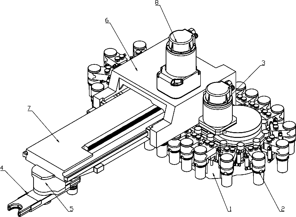
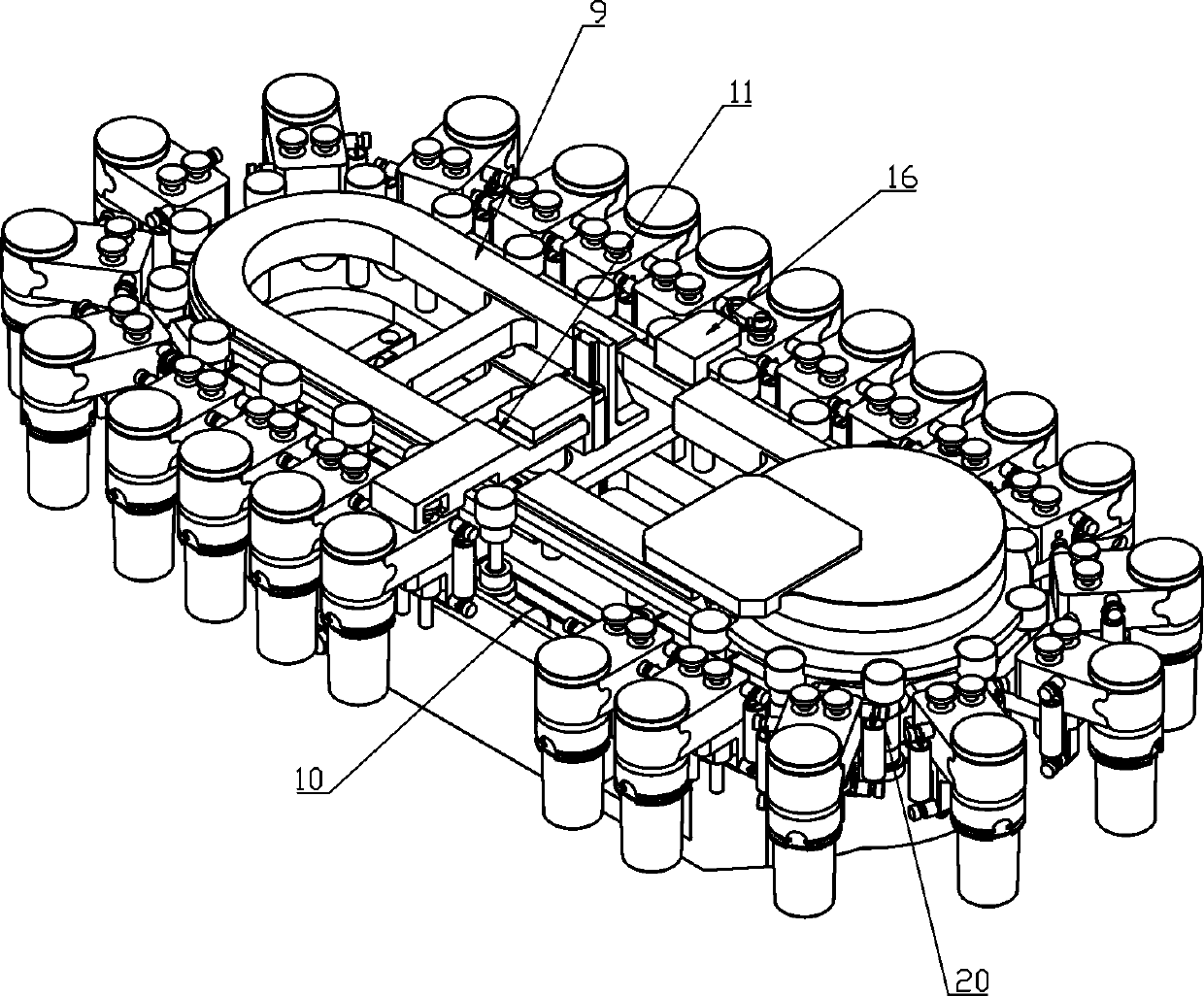
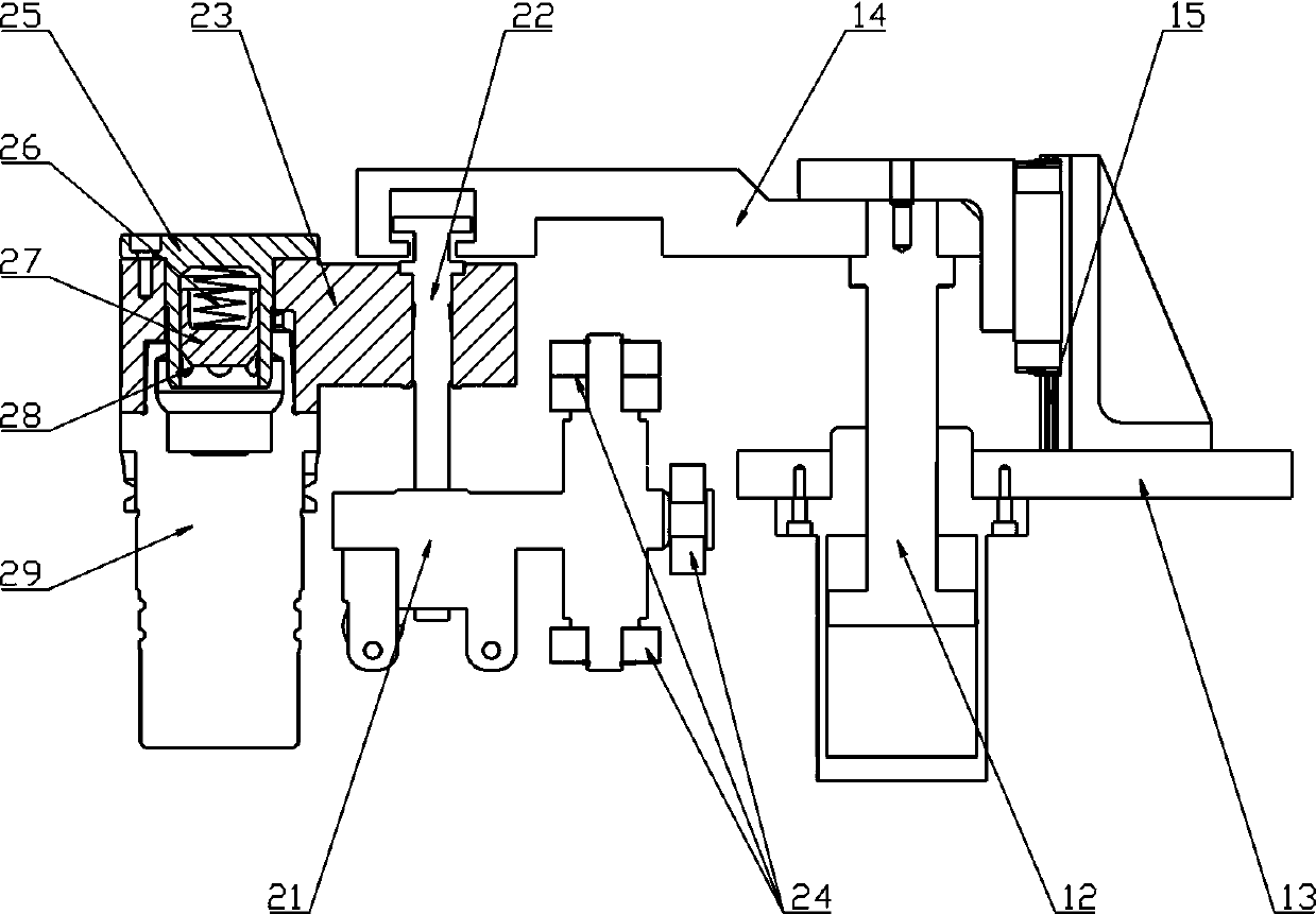
[0020] combine Figure 1 to Figure 2 As shown, an integrated chain tool magazine for self-picking and tool change of the present invention consists of a base 1, a chain mechanism 2, a chain drive unit 3, a tool changing manipulator 4, a manipulator rotation drive unit 5, a push-out slide 6, The ejection slide plate 7, the mobile ejection drive unit 8, the annular slide rail 9 and the guide groove 10 are composed.

[0021] The ring-shaped slide rail 9 is fixed on the base 1, and the chain mechanism 2 is arranged around the ring-shaped slide rail 9, which can rotate along the ring-shaped slide rail 9 under the action of the chain drive unit 3, and is guided by the guide groove 10 in the full stroke, effectively reducing the Noise and chatter during chain mechanism 2 rotation.

[0022] The push-out sliding seat 6 and the push-out slide...


PUM


Abstract

The invention relates to an integrated chain type tool magazine capable of automatically picking up and replacing tools, and aims to provide an integrated chain type tool magazine which is simple in structure, small in occupied space, low in manufacturing cost, high in tool replacing speed and small in tool replacing impact force. The integrated chain type tool magazine can be arranged right behind a machine tool, symmetrical arrangement of the machine tool is realized, machine tool precision loss caused by eccentricity is avoided, and an automatic production line is easy to arrange. The device is composed of a base, a chain mechanism, a chain driving unit, a tool replacing manipulator, a manipulator rotation driving unit, a manipulator moving push-out mechanism and a moving push-out driving unit, wherein the chain mechanism used for containing tools is arranged on the base and can rotate under the action of the chain driving unit; the tool replacing manipulator is installed on the base through the manipulator moving push-out mechanism, on one hand, push-out and returning linear reciprocating movement can be conducted under the action of the moving push-out driving unit, on the other hand, 180-degree rotation can be conducted under the action of the manipulator rotation driving unit, and tool position exchange is achieved.

Description

technical field [0001] The invention belongs to the field of numerical control machining, and in particular relates to an integrated chain tool magazine for self-picking and tool change. Background technique [0002] Due to its large capacity, the chain tool magazine has been more and more widely used in CNC machining centers. The existing chain-type tool magazine is mostly used with the tool-changing manipulator to realize tool exchange. The tool-changing manipulator and the chain-type tool magazine are designed independently. The tool-changing manipulator is located between the chain-type tool magazine and the machine tool spindle. The rotary motion of the manipulator arm completes tool removal, tool preparation and tool exchange. On the one hand, this structure is complex, takes up a large space overall, requires high positioning accuracy, and high manufacturing costs; on the other hand, the process of tool change and preparation is complicated, and the speed of tool cha...

Claims


Application Information

Patent Timeline
Patent Type & Authority Applications(China)
IPC IPC(8): B23Q3/155
CPCB23Q3/15534B23Q3/1554B23Q2003/15527B23Q3/15724
Inventor 陈学斌房大正王松雷志国高利飞
Owner 北京精雕精密机械制造有限公司
Learn More