
Fast tool servo device with adjustable rigidity

An adjustable, servo technology, used in metal processing machinery parts, metal processing equipment, feeding devices, etc., can solve problems such as can not be adjusted according to specific conditions

Inactive Publication Date: 2012-07-04
GUANGDONG UNIV OF TECH
View PDF5 Cites 36 Cited by
  • Summary
  • Abstract
  • Description
  • Claims
  • Application Information

AI Technical Summary

Problems solved by technology

The stiffness of the system is set during design and cannot be adjusted according to specific conditions during use

Method used


Image

  • Fast tool servo device with adjustable rigidity
  • Fast tool servo device with adjustable rigidity

Examples


Embodiment Construction

[0020] Below in conjunction with accompanying drawing, the present invention is described in further detail:

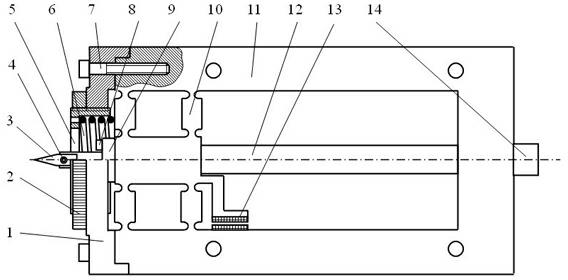
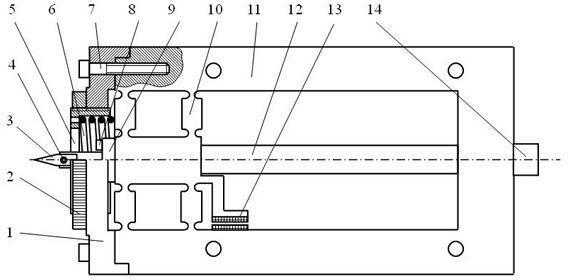
[0021] Cut out the frame 11 and the flexible hinge 10 on a whole piece of metal. On the central axis of the frame 11, the piezoelectric ceramic 12 is installed between the back beam of the frame 11 and the flexible hinge 10, and the other end of the flexible hinge 10 is connected to the tool holder. 9. Install prestressed bolts 14 on the rear beam of the frame 11 and connect the other end of the piezoelectric ceramic 12; the prestressed force can be adjusted through the prestressed bolts 14. The front end of the frame 11 is equipped with a knife rest assembly, and the diamond tool 3 is supported by the knife rest assembly and connected to the knife seat 9; the flexible hinge 10 is connected to the sensor 13 . The position sensor 13 can be used to detect the displacement of the flexible hinge. This displacement is the displacement of the diamond tool.

[0022] The sp...


PUM


Abstract

The invention discloses a fast tool servo device with adjustable rigidity. According to the device, a tool rest component is additionally arranged on an assembly of a frame, a flexible hinge, piezoelectric ceramic, a tool holder, a diamond cutting tool and the like, and comprises a spring bracket, a spring sleeve, a spring, a locking ring and the like; the spring bracket is arranged at the front end of the frame; the middle part of the spring bracket is provided with a threaded hole; the spring sleeve is matched with the threaded hole through external thread on the wall of the sleeve; the spring is arranged in the spring sleeve; one end of the spring is in contact with the bottom of an inner hole of the spring sleeve, and the other end of the spring is in contact with the flexible hinge on the frame; and pressure which is applied to the flexible hinge by the spring can be adjusted by turning the spring sleeve, so that the rigidity of the fast tool servo device is adjusted.

Description

technical field [0001] The invention relates to a fast knife servo with adjustable stiffness. Background technique [0002] The general fast tool servo refers to the fast tool servo system (fast tool servo, FTS), also known as fast tool servo system, micro-feed servo system or fast servo tool holder. Install FTS on the non-circular CNC turning or asymmetric turning machine tool. During the turning process, the spindle drives the workpiece to rotate, and the tool is driven by the FTS along the radial direction of the workpiece (for non-circular turning) or the axis at the frequency associated with the spindle speed. Reciprocating feed motion in the direction (for non-axisymmetric turning) to process non-circular cross-sectional profiles or non-axisymmetric end faces of the workpiece. In non-circular CNC turning, the application of FTS can process internal combustion engine piston contours, camshafts, cams, non-circular bearing inner contours, etc. In non-axisymmetric turnin...

Claims


Application Information

Patent Timeline
IPC IPC(8): B23Q5/22
Inventor 李克天陈新陈新度刘强
Owner GUANGDONG UNIV OF TECH
Learn More