Liquid injector, and medical device

一种喷射装置、液体的技术,应用在印刷、脉冲持续时间/宽度调制、电气元件等方向,能够解决放大率变化、不能驱动波形信号生成驱动信号、不能稳定驱动波形信号等问题,达到实现紧凑的效果

Inactive Publication Date: 2012-07-04
SEIKO EPSON CORP
View PDF9 Cites 0 Cited by
  • Summary
  • Abstract
  • Description
  • Claims
  • Application Information

AI Technical Summary

Problems solved by technology

[0007] However, in the above-mentioned prior art, there is a problem that the drive waveform signal cannot be amplified to a voltage higher than the power supply voltage to generate the drive signal, and the drive signal cannot be generated stably without being affected by ambient temperature, element temperature, and manufacturing variation.
Due to the high Q value of the LC resonance, the amplification factor changes greatly when the resonance frequency changes.
Therefore, it is not possible to stably amplify the power of the driving waveform signal to generate the driving signal

Method used


Image

  • Liquid injector, and medical device
  • Liquid injector, and medical device
  • Liquid injector, and medical device

Examples


Embodiment Construction

[0037] Hereinafter, in order to clarify the contents of the present invention described above, examples will be described in the following order.

[0038] A. Device structure:

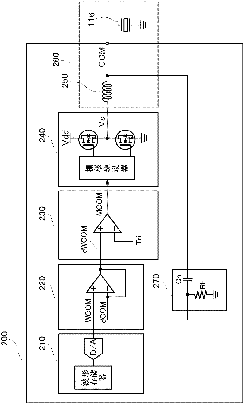
[0039] B. The circuit structure of the capacitive load drive circuit:

[0040] C. Action of capacitive load drive circuit:

[0041] D. Variations:

[0042] D-1. The first modified example:

[0043] D-2. Second modified example:

[0044] A. Device structure:

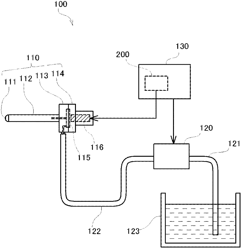
[0045] figure 1 It is an explanatory diagram showing the configuration of the liquid ejection apparatus 100 equipped with the capacitive load drive circuit 200 of the present embodiment. As shown in the figure, the liquid ejection device 100 is roughly composed of an ejection unit 110 that ejects liquid, a supply pump 120 that supplies the liquid ejected from the ejection unit 110 to the ejection unit 110, and a control unit 130 that controls the operations of the ejection unit 110 and the supply pump 120. and so on. For example, the spray...


PUM


Abstract

The invention provides a liquid injector, and a medical device that can generate a drive signal having a voltage exceeding a power supply voltage and generate a stable drive signal without being affected by the ambient temperature and manufacturing variations of parts. A drive waveform signal is pulse-modulated and a modulated signal is generated, the obtained modulated signal is power-amplified, and then, a drive signal is demodulated using a low pass filter. Thus obtained drive signal is negatively fed back, and thereby, the resonance peak of the low pass filter is suppressed. In this regard, by bringing gain in a wider frequency domain to take a fixed value or more, a drive signal having a voltage exceeding a power supply voltage may be stably generated.

Description

technical field [0001] The present invention relates to a technique for driving a capacitive load whose capacitance component varies, or a technique for switching and driving a plurality of capacitive loads with different capacitance components. Background technique [0002] There are many actuators that operate by applying a predetermined drive signal to eject liquid or the like, such as an ejection head mounted on an inkjet printer. The operation of the actuator depends on the applied voltage. Therefore, it is desirable to be able to apply a high voltage in order to fully exhibit the performance of the actuator. Therefore, the power of the driving waveform signal applied to the actuator is amplified and then applied to the actuator. [0003] As a method of amplifying the power of a drive waveform signal, for example, a method using a class D amplifier is disclosed (Patent Document 1, etc.). In this method, a drive waveform signal is pulse-modulated to be converted into a...

Claims


Application Information

Patent Timeline
Patent Type & Authority Applications(China)
IPC IPC(8): B41J2/045
CPCH03K17/166H03K7/08
Inventor 大岛敦
Owner SEIKO EPSON CORP
Why Eureka
Try Eureka