
Pull type clutch release bearing capable of injecting grease for lubricating

A release bearing and clutch technology, applied in the direction of clutches, mechanically driven clutches, bearing components, etc., can solve the problems of release bearing failure, release bearing grease failure loss, release bearing internal temperature rise, etc., achieve good lubrication performance and prolong service life The effect of longevity

Active Publication Date: 2012-07-04
WUXI MINLIAN AUTOMOBILE PARTS CO LTD
View PDF5 Cites 7 Cited by
  • Summary
  • Abstract
  • Description
  • Claims
  • Application Information

AI Technical Summary

Problems solved by technology

However, in the actual use process, the release bearing generates high temperature, resulting in the failure of the release bearing still exists, especially in mining trucks
The fundamental reason is that the domestic vehicles are generally overloaded, the road conditions in mining areas are poor, the vehicles are driving on multi-slope roads, the driver frequently disengages the clutch for a long time, slides downhill in neutral gear, climbs in a semi-linkage method, and the clutch is half-clutched for a long time state, the two operation methods cause the internal temperature of the clutch assembly to rise sharply; at the same time, because the clutch is in the disengaged and semi-clutch state for a long time, the release bearing will rotate at a high speed for a long time under high load, resulting in an increase in the internal temperature of the release bearing
Under the action of high temperature both inside and outside, the grease inside the release bearing fails and loses, and the lubrication performance is lost, resulting in the release bearing burning and failure

Method used


Image

  • Pull type clutch release bearing capable of injecting grease for lubricating
  • Pull type clutch release bearing capable of injecting grease for lubricating
  • Pull type clutch release bearing capable of injecting grease for lubricating

Examples


Embodiment Construction

[0017] The specific embodiments of the present invention will be further described below in conjunction with the accompanying drawings.

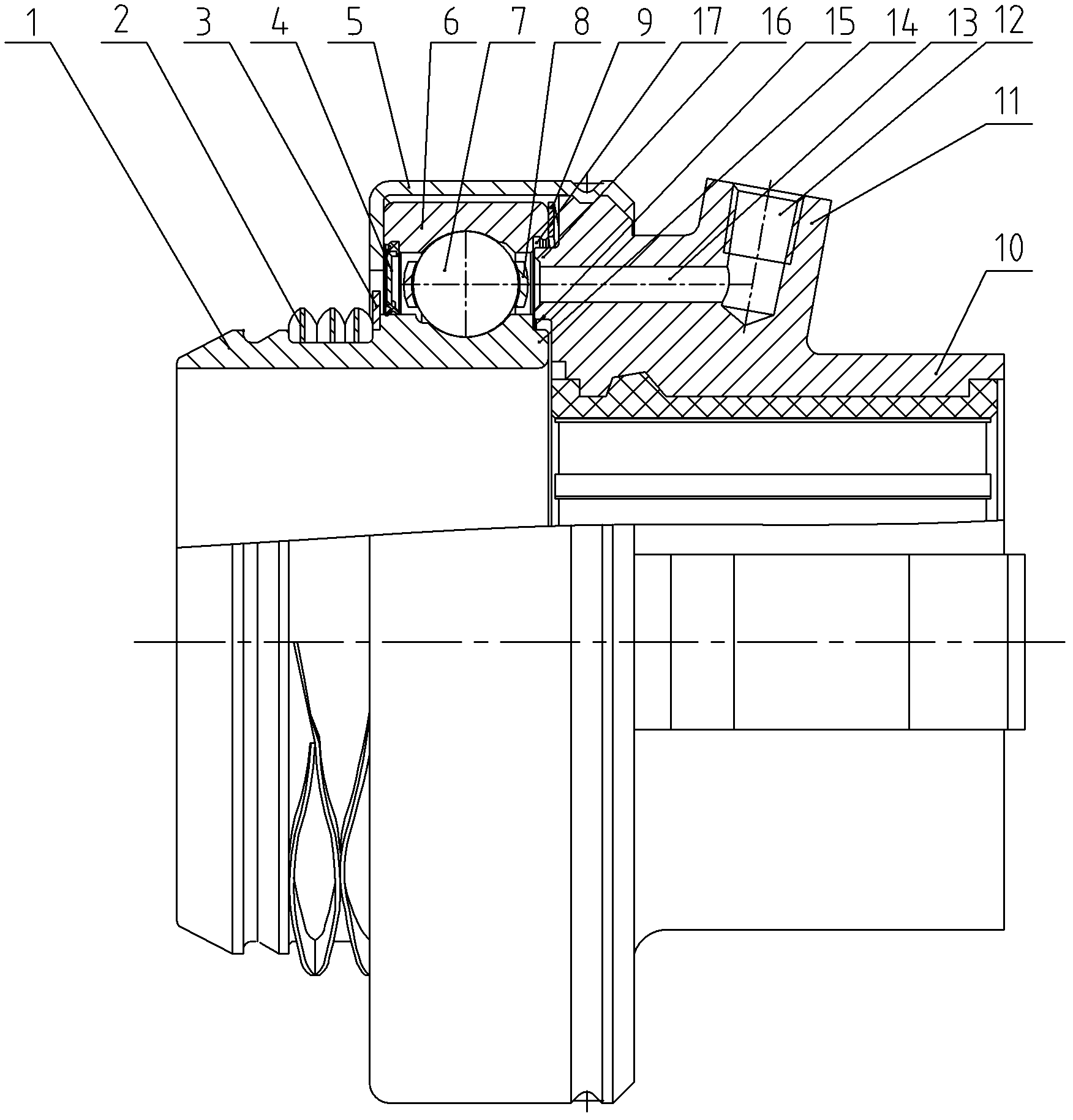
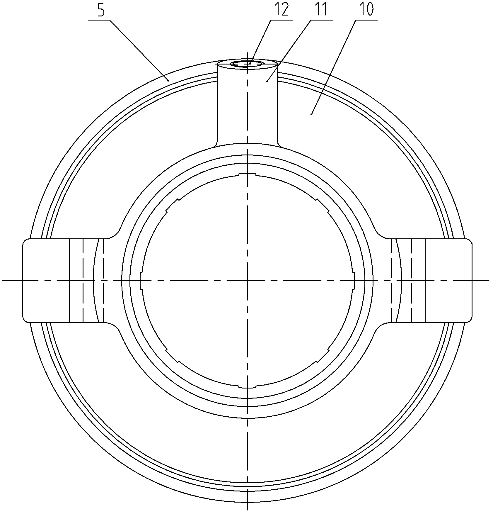
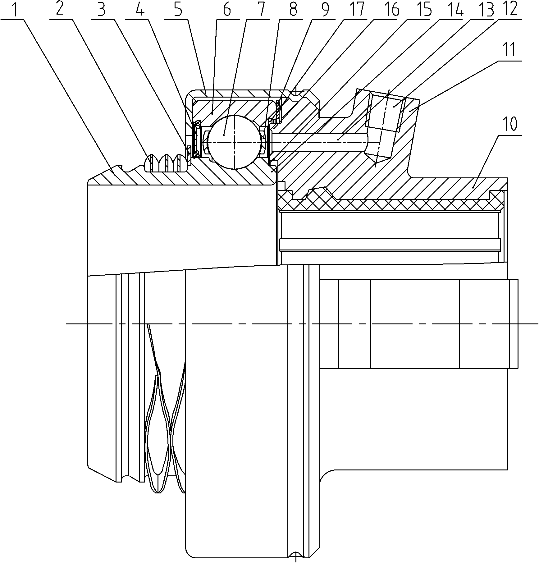
[0018] figure 1 , figure 2 , including bearing inner ring 1, compression spring 2, support ring 3, seal ring 4, housing 5, bearing outer ring 6, ball 7, cage 8, support spring 9, separation sleeve 10, boss 11, note Grease hole 12, grease guide cylindrical hole 13, shaft shoulder 14, ring groove 15, protruding ring 16, pit 17, etc.

[0019] Such as figure 1 , figure 2 As shown, the present invention is a grease-lubricated pull-type clutch release bearing, which includes a release sleeve 10 , a bearing outer ring 6 , balls 7 and a bearing inner ring 1 located on one side of the release sleeve 10 .

[0020] The bearing outer ring 6 is set outside the bearing inner ring 1. The outer surface of the bearing inner ring 1 is provided with a circumferential outer groove, and the inner surface of the bearing outer ring 6 is provided with a circu...


PUM


Abstract

The invention relates to a pull type clutch release bearing capable of injecting grease for lubricating, which includes a release sleeve and a bearing outer ring, a ball and a bearing inner ring that are positioned on one side of the release sleeve, wherein a seal ring is arranged between the bearing outer ring and the bearing inner ring on the outer side of the ball; a support spring is arrangedbetween the bearing outer ring and the end surface of the release sleeve; a housing is fixed between the outer end surface of the bearing outer ring and the outer wall surface of the release sleeve; an annular groove is arranged on the inner side end surfaces of the bearing outer ring and the bearing inner ring; a convex ring in clearance fit with the annular groove is arranged on inner side end surface of the release sleeve; and a grease injecting hole communicated with the inside of the annular groove is formed in the release sleeve. By forming the grease injecting hole communicated with the interior of the release bearing in the release bearing, when the lubricating grease in the release bearing fails and flows away due to high temperature during the use of the release bearing, the lubricating grease can be timely replenished to the interior of the release bearing through the grease injecting hole, so as to retain the excellent lubricating performance of the bearing, and prolong the service life of the release bearing.

Description

technical field [0001] The invention relates to a pull-type clutch release bearing used on medium and heavy vehicles, in particular to a grease-lubricated pull-type clutch release bearing used on a mine truck. Background technique [0002] The release bearing of the pull clutch is often lubricated with grease. There is a certain amount of grease in the inner and outer raceways of the bearing, so that the release bearing has good lubricating performance, thereby suppressing the generation of high temperature. However, in the actual use process, the high temperature generated by the release bearing still exists, which leads to the failure of the release bearing, especially in the mining truck. The fundamental reason is that the domestic vehicles are generally overloaded, the road conditions in mining areas are poor, the vehicles are driving on multi-slope roads, the driver frequently disengages the clutch for a long time, slides downhill in neutral gear, climbs in a semi-linka...

Claims


Application Information

Patent Timeline
IPC IPC(8): F16D23/14F16C33/66F16C33/58
Inventor 邵济民
Owner WUXI MINLIAN AUTOMOBILE PARTS CO LTD
Learn More