Solar collector array

A solar collector and solar collector technology, applied in the field of solar collector arrays, can solve problems such as inconvenient maintenance of solar collector arrays, improve light-to-heat conversion efficiency, reduce losses, and facilitate inspection and maintenance Effect

Inactive Publication Date: 2012-07-04
YIKEBO ENERGY TECH SHANGHAI
View PDF4 Cites 2 Cited by
  • Summary
  • Abstract
  • Description
  • Claims
  • Application Information

AI Technical Summary

Problems solved by technology

[0004] The object of the present invention is to provide a solar thermal collector array to overcome the problem of inconvenient maintenance of solar thermal collector arrays in the prior art

Method used


Image

  • Solar collector array
  • Solar collector array
  • Solar collector array

Examples


Embodiment Construction

[0017] The specific embodiments of the present invention will be described in detail below in conjunction with the accompanying drawings.

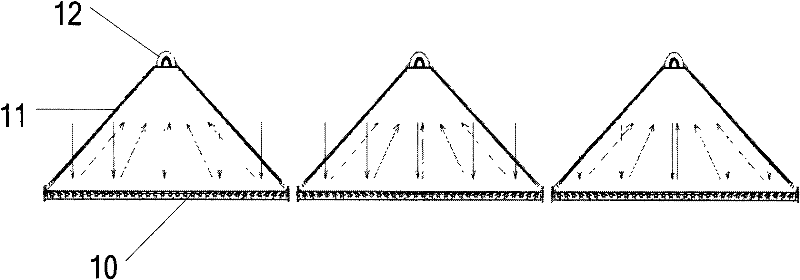
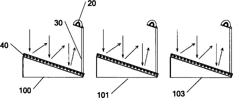
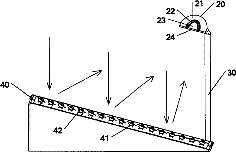
[0018] First, please refer to figure 2 , figure 2 It is the schematic diagram of solar heat collector array of the present invention, from figure 2 As can be seen above, the solar heat collector array of the present invention includes a plurality of solar heat collectors placed side by side, figure 2 Three solar thermal collectors 100, 101 and 102 placed side by side are listed in , taking the solar thermal collector 100 as an example, each of the solar thermal collectors includes a solar collector 40 and a solar receiver 20, and the solar thermal The collector 40 and the solar receiver 20 are connected by a support frame 30, and an acute angle is formed between the solar collector 40 and the ground. An acute angle is set between the solar collector 40 and the ground, mainly to facilitate the staff to inspect and repair the solar co...


PUM


Abstract

The invention provides a solar collector array, which comprises a plurality of solar collectors placed side by side. Each solar collector comprises a solar collector body and a solar receiver which are connected with each other by the aid of a support, and an acute angle is formed between each solar collector body and the ground, so that the whole solar collector array is convenient in examination and maintenance on the premise of ensuring solar thermal conversion efficiency.

Description

technical field [0001] The invention belongs to the field of solar energy equipment, and in particular relates to a solar heat collector array. Background technique [0002] Solar energy (Solar Energy), generally refers to the radiant energy of sunlight, which is generally used for power generation in modern times. Since the formation of the earth, organisms have mainly survived on the heat and light provided by the sun. Since ancient times, humans have also known to use sunlight to dry objects and use it as a method of preserving food, such as making salt and drying salted fish. But with the reduction of fossil fuels, there is an intention to further develop solar energy. The utilization of solar energy has two ways: passive utilization (photothermal conversion) and photoelectric conversion. Solar power is an emerging renewable energy source. In a broad sense, solar energy is the source of many energies on the earth, such as wind energy, chemical energy, potential energy...

Claims


Application Information

Patent Timeline
Patent Type & Authority Applications(China)
IPC IPC(8): F24J2/10F24J2/46F24S23/70
CPCY02E10/40
Inventor 项晓东任松林
Owner YIKEBO ENERGY TECH SHANGHAI
Why Eureka
Try Eureka