Rapid slag removing method of heating furnace

A heating furnace and slag removal technology, which is applied in the field of improving the efficiency of slag removal in steel rolling heating furnaces, can solve problems such as non-continuous operation, channel blockage, and long time for slag removal, so as to reduce labor intensity, improve slag removal efficiency, and improve operations. environmental effects

Active Publication Date: 2014-05-07
SHANXI TAIGANG STAINLESS STEEL CO LTD
View PDF6 Cites 0 Cited by
  • Summary
  • Abstract
  • Description
  • Claims
  • Application Information

AI Technical Summary

Problems solved by technology

The main problem is that the passageway of the steel platform with an elevation of -2.2m is only 600mm wide, and the four slag discharge points on each side cannot discharge slag at the same time, otherwise the passageway will be blocked
Only one slag hopper can be placed at the slag hanging point, and continuous operation cannot be carried out after it is filled and hoisted away
Therefore, it takes too long for each slag cleaning operation

Method used


Image

  • Rapid slag removing method of heating furnace
  • Rapid slag removing method of heating furnace
  • Rapid slag removing method of heating furnace

Examples


Embodiment Construction

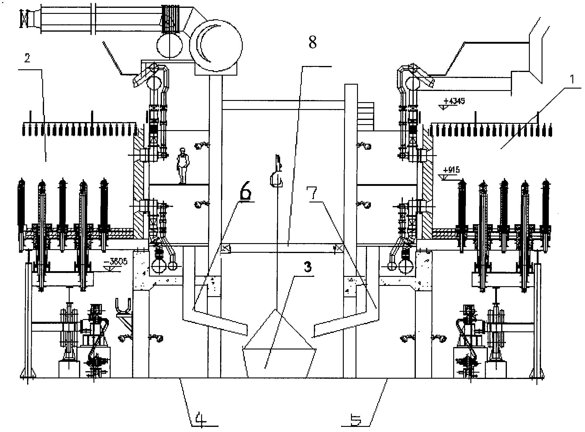
[0013] The new slag lifting point is at the bottom of the furnace with an elevation of -8.8m under the equipment hoisting hole. Two slag hoppers 3 are placed side by side at the new slag lifting point, and the two slag hoppers 3 are hoisted in turn for continuous operation.

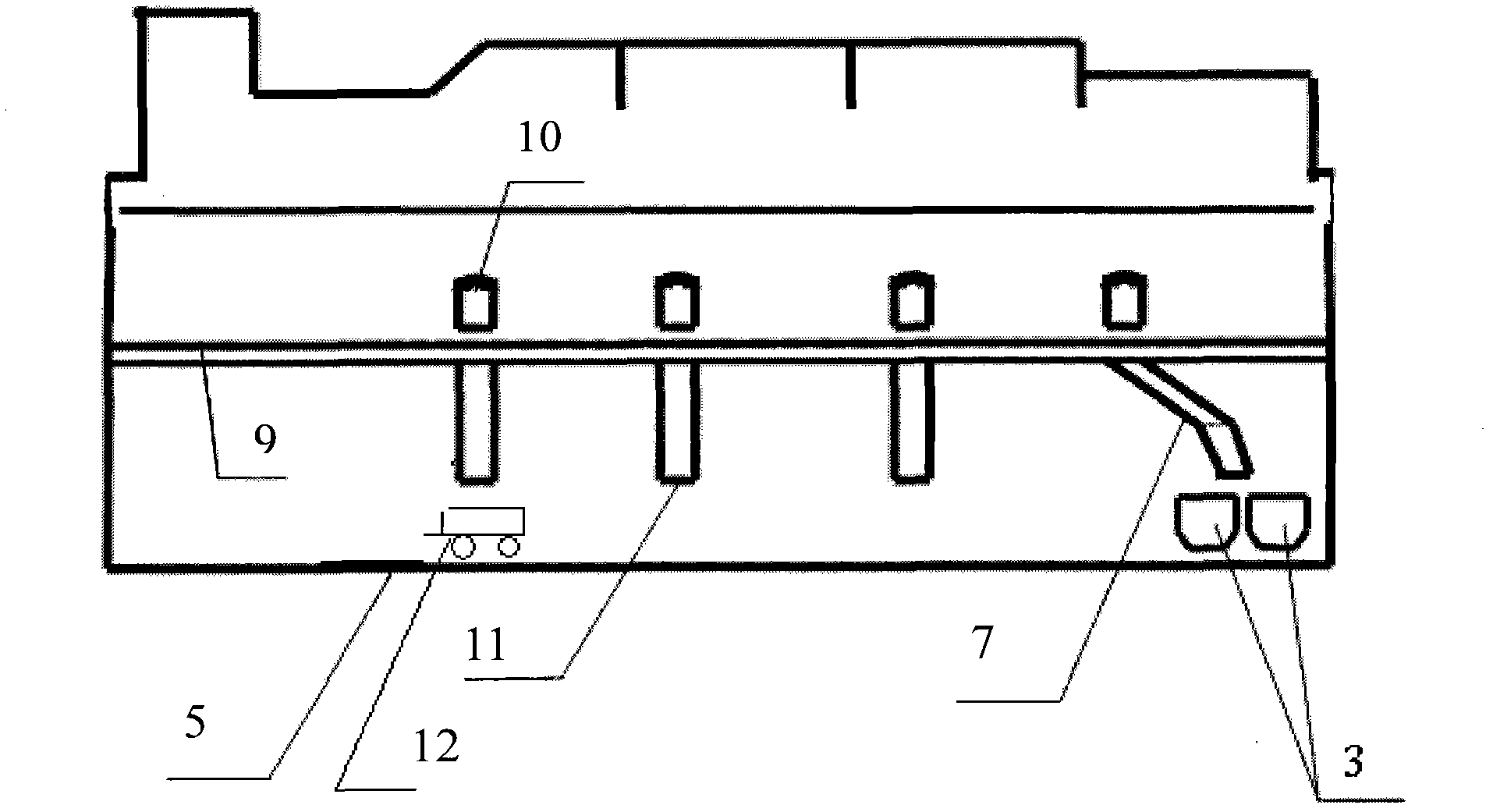
[0014] On the steel platform channel 9 with an elevation of -2.2m corresponding to the four slagging furnace doors on each side of each heating furnace, holes are respectively opened to install slag chute 7, 11, and slag chute 7, 11 is made of 8mm thick steel plate to make.

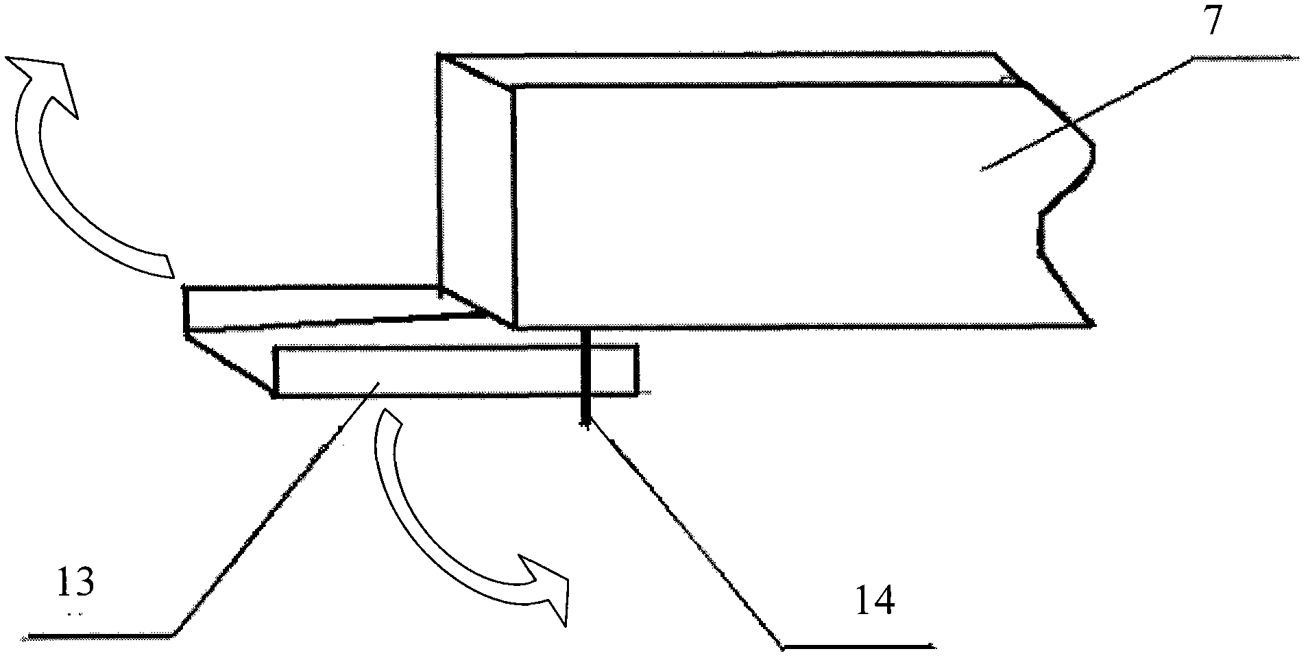
[0015] On the two slag chutes correspondingly installed outside the two slag discharge furnace doors in the soaking section, a movable guide chute 13 that can change the direction of slag chute is installed on each of the two slag chutes that can change the direction of slag chute. Inside the slag hopper 3; the remaining six slag chutes 11 directly slide the high-temperature steel slag into the slag transport trolley 12 placed at the...


PUM


Abstract

A rapid slag removing method of a heating furnace is disclosed, which aims at alleviating the labor intensity, improving the working environment and improving the slag removing efficiency. In the invention, four mounting holes are respectively arranged in slag discharging furnace doors corresponding to a steel platform channel outside the four slag discharging furnace doors on each side of the heating furnace, and two slag sliding grooves communicated to the bottom of the furnace are installed on each mounting hole, namely eight slag sliding grooves are arranged; two of the slag sliding grooves can change the slag sliding direction; these two slag sliding grooves enable half of the high-temperature steel slag in the furnace to directly and alternately slide in two slag hoppers which are arranged at the new slag hoisting points on the bottom of the furnace and are arranged in parallel, the other six slag sliding grooves enable the residual steel slag to slide in a slag transporting trolley arranged on the ground of the bottom of the furnace, the residual steel slag is transported to the new slag hoisting point and fed in the slag hoppers for hoisting, the two slag hoppers are hoisted by turns to work continuously, so that the slag removing efficiency of the heating furnace is improved.

Description

technical field [0001] The invention relates to a method for improving the slag cleaning efficiency of a steel rolling heating furnace. Background technique [0002] Steel rolling heating furnace is a common equipment in iron and steel enterprises. The general structure is that each heating furnace has four small slag doors on both sides. line maintenance time, and the slag removal operation of the heating furnace is the project with the most manpower and the most working hours in the annual maintenance projects of the whole line. The four small furnace doors on the north and south sides are cleared out, and stacked on the steel platform channel with an elevation of -2.2m on both sides of the furnace, and then the slag from each slag stacking point is transported to the crane slag at the furnace head through the steel platform channel point, put it into the slag bucket and hang it away after being concentrated. The current large-scale walking heating furnace is generally e...

Claims


Application Information

Patent Timeline
Patent Type & Authority Patents(China)
IPC IPC(8): C21B7/14F27D3/15
Inventor 张伟民陶毅清
Owner SHANXI TAIGANG STAINLESS STEEL CO LTD
Why Eureka
Try Eureka