Steel plate slag removal equipment

A technology for cleaning slag and equipment, applied in metal processing equipment, grinding/polishing equipment, grinding feed motion, etc., can solve the problems of inability to replace the slag cleaning alone, inability to protect operators, inconvenient loading and unloading, etc. The effect of cleaning slag time, easy loading and unloading, and large contact area

Pending Publication Date: 2021-12-28
GUANGZHOU ZENGLI STEEL STRUCTURE
View PDF5 Cites 0 Cited by
  • Summary
  • Abstract
  • Description
  • Claims
  • Application Information

AI Technical Summary

Problems solved by technology

[0004] The purpose of the present invention is to provide a steel plate slag removal equipment, which has the advantages of convenient loading and unloading, protection, large contact area and the advantages of separately replacing the slag cleaning nails, which solves the problem that the current steel plate slag cleaning equipment is not convenient for loading and unloading, and cannot The protection of operators, the small contact area and the inability to replace the slag alone

Method used


Image

  • Steel plate slag removal equipment
  • Steel plate slag removal equipment
  • Steel plate slag removal equipment

Examples


Embodiment 1

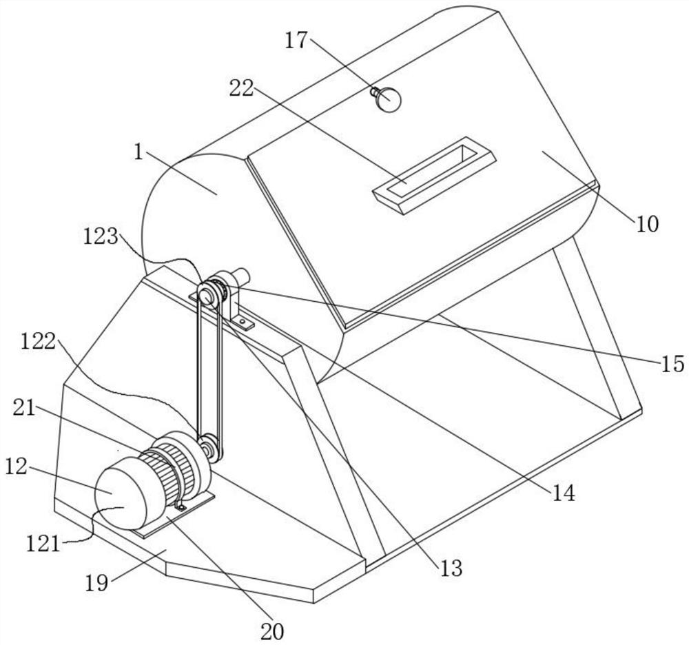
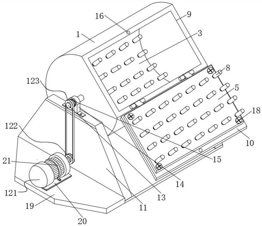
[0027] see Figure 1-2 As shown, a steel plate slag removal equipment includes a slag removal drum 1, the surface of the slag removal drum 1 is provided with a feeding groove 9, and through the setting of the feeding groove 9, the user can directly pass through the feeding groove 9. The material is put into the inside of the slag cleaning drum 1, and one side of the feeding chute 9 is hinged with a cover plate 10 through a hinge. Prevent external impurities from entering the inside of the slag cleaning drum 1 when not in use, and at the same time prevent the steel plates and steel slag inside the slag cleaning drum 1 from splashing out, install the arc plate 1, install the arc plate 2 3, There are four installation screws 23 connected with the internal thread of the slag cleaning drum 1, and the inside of the installation arc plate three 4 is threaded. By setting the limit bolt 17, it is convenient for the operator to install the arc plate one 2, The installation and disassem...

Embodiment 2

[0029] see Figure 1-4As shown, a steel plate slag removal equipment includes a slag removal drum 1, the surface of the slag removal drum 1 is provided with a feeding groove 9, and through the setting of the feeding groove 9, the user can directly pass through the feeding groove 9. The material is put into the inside of the slag cleaning drum 1, and one side of the feeding chute 9 is hinged with a cover plate 10 through a hinge. Prevent external impurities from entering the inside of the slag cleaning drum 1 when not in use, and at the same time prevent the steel plates and steel slag inside the slag cleaning drum 1 from splashing out, install the arc plate 1, install the arc plate 2 3, There are four installation screws 23 connected with the internal thread of the slag cleaning drum 1, and the inside of the installation arc plate three 4 is threaded. By setting the limit bolt 17, it is convenient for the operator to install the arc plate one 2, The installation and disassemb...

Embodiment 3

[0031] see Figure 1-5 As shown, a steel plate slag removal equipment includes a slag removal drum 1, the surface of the slag removal drum 1 is provided with a feeding groove 9, and through the setting of the feeding groove 9, the user can directly pass through the feeding groove 9. The material is put into the inside of the slag cleaning drum 1, and one side of the feeding chute 9 is hinged with a cover plate 10 through a hinge. Prevent external impurities from entering the inside of the slag cleaning drum 1 when not in use, and at the same time prevent the steel plates and steel slag inside the slag cleaning drum 1 from splashing out, install the arc plate 1, install the arc plate 2 3, There are four installation screws 23 connected with the internal thread of the slag cleaning drum 1, and the inside of the installation arc plate three 4 is threaded. By setting the limit bolt 17, it is convenient for the operator to install the arc plate one 2, The installation and disassem...


PUM


Abstract

The invention relates to the technical field of slag removal equipment, and discloses steel plate slag removal equipment which comprises a slag removal rotary drum, a feeding groove is formed in the surface of the slag removal rotary drum, and a cover plate is hinged to one side of the feeding groove through a hinge. By forming the feeding groove in the surface of the slag removal rotary drum and shielding the feeding groove with the cover plate, the equipment can prevent steel plates and steel slag in the slag removal rotary drum from splashing out to accidentally injure workers, the safety performance of the equipment during use is improved, and the workers can complete discharging at a time. The repeated discharging process is avoided. A mounting arc-shaped plate I, a mounting arc-shaped plate II, a mounting arc-shaped plate III and a mounting plate which are internally provided with a plurality of slag removal nails are arranged in the slag removal rotary drum, so that the contact area between the slag removal nails in the equipment and the steel plates is increased, the equipment can carry out slag removal on the steel plates in all directions, and the slag removal time of the equipment is shortened. And the slag removal efficiency of the equipment is improved.

Description

technical field [0001] The invention relates to the technical field of slag removal equipment, in particular to a steel plate slag removal equipment. Background technique [0002] In the steel structure, the blanking method of steel plate and section steel is generally processed by thermal cutting, and after thermal cutting, defects such as molten nodules and slag will remain on the cutting end surface of the workpiece; however, the usual method of removing the above defects is manual hand-held grinding machine Grinding and cleaning, the work intensity is high, the grinding efficiency is low, and the splash produced by grinding has certain hidden dangers to personal safety. [0003] At present, the slag removal equipment for steel plates is not convenient for loading and unloading steel materials, and cannot protect the operators. During use, the operators need to repeatedly put the steel plates into the equipment one by one, and the equipment is in In the process of slag c...

Claims


Application Information

Patent Timeline
Patent Type & Authority Applications(China)
IPC IPC(8): B24B27/033B24B41/00B24B55/00
CPCB24B27/033B24B41/005B24B55/00
Inventor 杜连喜吴凡张帝起
Owner GUANGZHOU ZENGLI STEEL STRUCTURE
Why Eureka
Try Eureka