Device for detecting position of broken roller of kiln

A detection device and a technology for broken rolls, applied in furnaces, furnace components, lighting and heating equipment, etc., can solve the problems of high cost of electric eyes, burning of electric eyes, cumbersome adjustments, etc., and achieve the effect of safe use, economic benefits, and simple materials

Active Publication Date: 2012-07-04
GUANGDONG JUMPER THERMAL TECH
View PDF4 Cites 2 Cited by
  • Summary
  • Abstract
  • Description
  • Claims
  • Application Information

AI Technical Summary

Problems solved by technology

The disadvantages are: 1. The laser beam is very thin, and the adjustment is cumbersome; 2. The high-temperature zone of the kiln is under positive pressure. If the roller is r

Method used


Image

  • Device for detecting position of broken roller of kiln
  • Device for detecting position of broken roller of kiln
  • Device for detecting position of broken roller of kiln

Examples


Embodiment Construction

[0013] The following descriptions are only preferred embodiments of the present invention, and therefore do not limit the protection scope of the present invention.

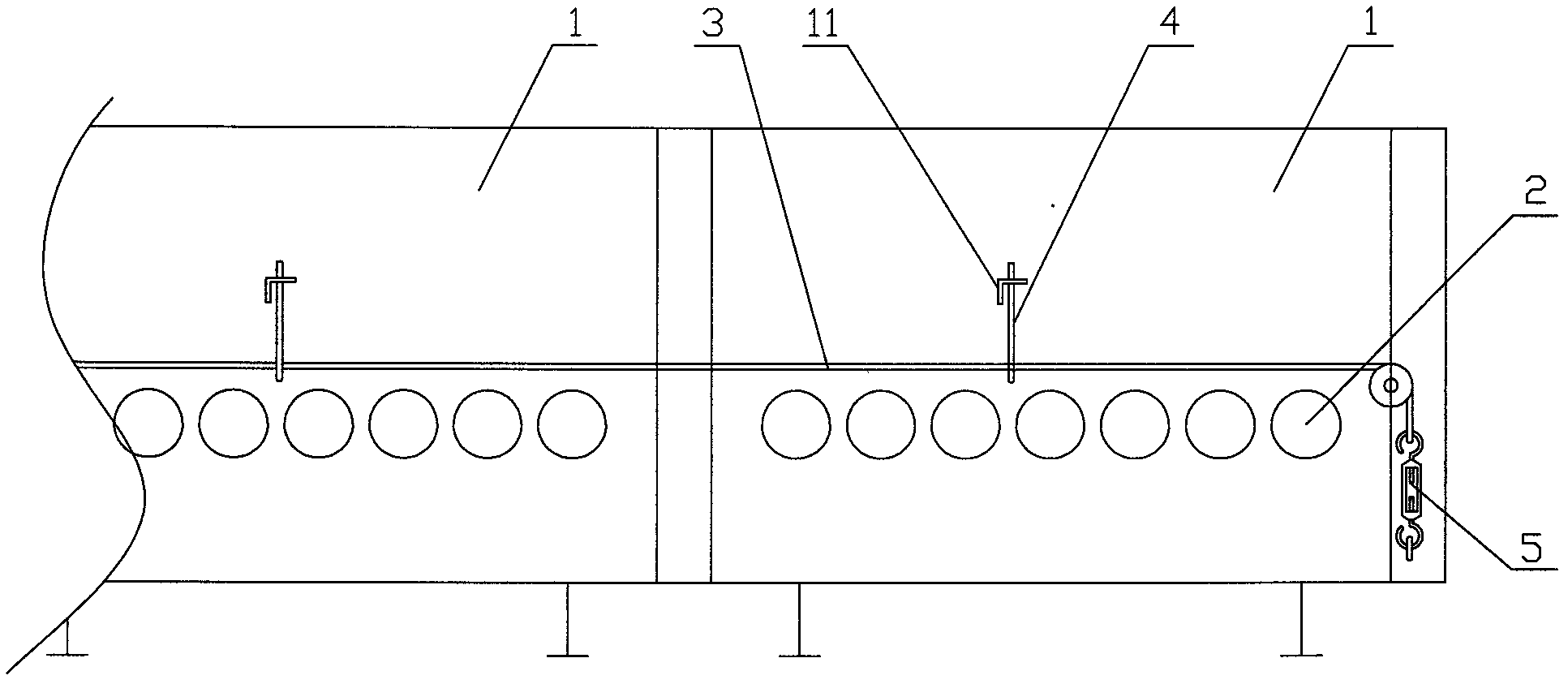
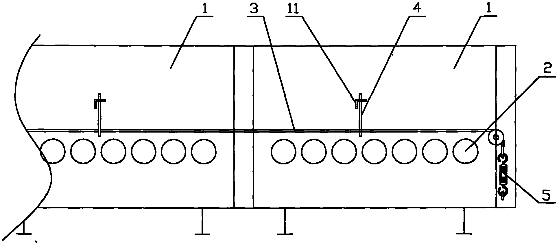
[0014] Examples, see figure 1 and figure 2 Shown: The kiln roller broken position detection device, including at least two kiln body units 1 connected together, each kiln body unit 1 is equipped with a roller bar 2, and the end of the roller bar 2 protrudes from the kiln body unit 1 outside the sidewall.

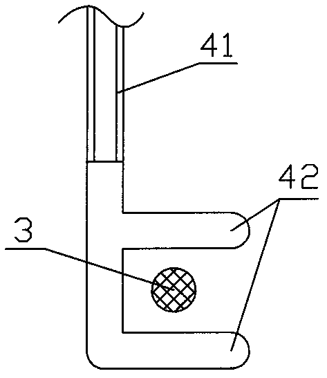
[0015] All kiln body units 1 are insulated from each other. A steel frame seat 11 is connected to the side wall of the kiln body unit 1, and a steel wire frame 4 is connected to the steel frame seat 11. The side of the wire rack 4 is provided with a metal "U"-shaped opening 42 , that is, the opening of the "U"-shaped opening 42 faces the side of the wire rack 4 . All "U"-shaped openings 42 are located on the same straight line, and the same tensioned steel wire 3 passes through all "U"-shaped openings 42 ....


PUM


Abstract

The invention discloses a device for detecting a position of a broken roller of a kiln. The device comprises at least two kiln body units which are connected together, wherein a roller is arranged in each kiln body unit; end parts of the roller are extended out of a side wall of each kiln body unit; all kiln body units are insulated from one another; a steel frame base is arranged above each kiln body unit; a steel wire frame is connected to the steel frame base; a metal U-shaped opening is reserved on one side of the steel wire frame; all the U-shaped openings are positioned on the same straight line; the same tightened steel wire passes through all the U-shaped openings; a gap is reserved between the steel wire and a side wall of each U-shaped opening; and meanwhile, the steel wire is positioned on the upper side of each end part of the roller, and each U-shaped opening and the steel wire are connected to a display device. Optimally, the display device is a computer. Due to the structure, the invention has the advantages that the device is economical and practical, is convenient to assemble and adjust, and is safely used.

Description

technical field [0001] The invention relates to the technical field of kiln detection devices, in particular to a kiln broken roll position detection device. Background technique [0002] The kiln includes at least two kiln body units connected together, each kiln body unit is provided with a roller, and the end of the roller sticks out of the side wall of the kiln body unit. Roll breakage (disconnection of the roll bar) is a common failure during use. Due to the long length of the kiln, in order to find the position of the broken roll in time, the current common practice is to use the method of laser shooting. That is to install an electric eye at both ends of the kiln, one of which emits laser light and the other receives laser light. When there is a broken rod, the end of the roller sticks up, which hinders the passage of the electric eye laser, so that the signal is transmitted to the computer, and then the computer displays and alarms. The disadvantages are: 1. The l...

Claims


Application Information

Patent Timeline
IPC IPC(8): F27D21/00
Inventor 万鹏
Owner GUANGDONG JUMPER THERMAL TECH
Why Eureka
Try Eureka