Machining tool detection method

A technology for machining tools and detection methods, applied in the field of detecting whether the machining tools are formed correctly, can solve the problems of damage to the machining tools, inability to cut the machining tools, inaccurate machining, and inaccurate inspection work, and achieve the effect of a small error range

Inactive Publication Date: 2012-07-04
TOPOINT TECH
View PDF5 Cites 12 Cited by
  • Summary
  • Abstract
  • Description
  • Claims
  • Application Information

AI Technical Summary

Problems solved by technology

[0004] (2) If the size, angle, length or shape of the processing tool is too large, it is easy to cause the processing tool to be unable to cut and process during the actual processing operation, and may also cause the processing tool to be damaged or broken. dangerous situation
[0005] Therefore, how to solve the problem that the current processing tools cannot be accurately detected after grinding, refurbishment, etc., and the processing tools can only rely on manual visual inspection to meet the lack of accurate specifications, and must be improved, that is, the inventors and Relevant manufacturers engaged in this industry are eager to study the direction of improvement

Method used


Image

  • Machining tool detection method
  • Machining tool detection method
  • Machining tool detection method

Examples


Embodiment Construction

[0041] In order to achieve the above-mentioned purpose and effect, the technical means adopted by the present invention and its implementation mode, the features and functions of the preferred embodiments of the present invention will be described in detail as follows in order to facilitate a complete understanding.

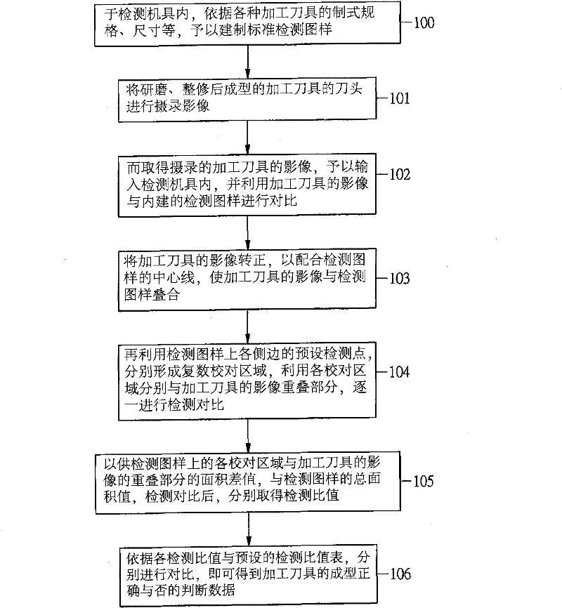
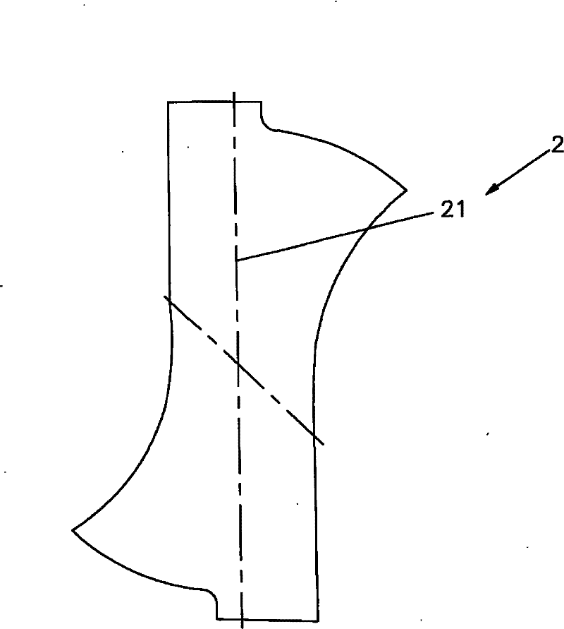
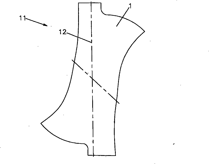
[0042] see figure 1 , figure 2 , image 3 Shown, is the flow chart of the present invention, the plan view of standard detection pattern, processing tool camera image picture and the detection system figure (1) of the actual application of the present invention, the detection system figure (2) of actual application, the detection of actual application System diagram (three), can clearly find out by shown in the figure, the machining tool detection method of the present invention, its detection step is:

[0043] (100) In the testing machine tool, according to the standard specification, size, etc. of various processing tools 1, a standard testing pattern 2 is p...


PUM


Abstract

The invention relates to a machining tool detection method, which includes: setting a standard detection pattern in a detector; and inputting a shot image of a formed machining tool into the detector for comparison. The image of the machining tool needs to be rotated first so that a center line of the image fits a center line of the detection pattern in an overlapped combination manner, a plurality of calibration areas formed on lateral edges of the detection pattern can be subjected to detection comparison with overlapped parts of the image of the machining tool, a difference between the area of the calibration areas and the area of the overlapped parts of the machining tool is compared with a total area value of the detection pattern to obtain a detection specific value, and the detection specific value is subjected to comparison and analysis with a preset detection value so as to obtain a determination data of the machining tool, so that the machining tool is detected accurately, and the service life of a grinder for forming the machining tool can be determined.

Description

technical field [0001] The invention relates to a method for detecting whether the shape of a processing tool is correct, especially a detection method for comparing and analyzing formed processing tools, using the ratio of the image of the processing tool and the built-in detection pattern of the detection machine to achieve the detection of the accuracy of the processing tool purpose, and at the same time check the service life of the grinding equipment. Background technique [0002] In various mechanical processing operations, in addition to basic lathe, fitter, welder and other processing procedures, drilling or milling processing methods are often used when manufacturing finished products, regardless of the implementation of the processing operations. It is necessary to use processing tools for operations, such as drill bits or milling cutters used in drilling and milling, the most commonly used processing tools in general machining, and the processing tools of drill bi...

Claims


Application Information

Patent Timeline
Patent Type & Authority Applications(China)
IPC IPC(8): G01B11/24G01B11/02G01B11/26G01B11/00G01B11/28
Inventor 钟任超吕家庆
Owner TOPOINT TECH
Why Eureka
Try Eureka