Mueller matrix testing device based on rotatable wave plate and method

A technology of rotating wave plate and measuring device, which is applied in the direction of testing optical performance, etc., can solve problems affecting test results, etc., and achieve the effect of strict and accurate parameter values, loose range, and simple and easy implementation and testing process

Inactive Publication Date: 2012-07-04
SHANGHAI UNIV
View PDF2 Cites 28 Cited by
  • Summary
  • Abstract
  • Description
  • Claims
  • Application Information

AI Technical Summary

Problems solved by technology

Therefore, the biggest feature of these test methods is the alignment requirement for the polarization axis of the optical system. During the measurement, it is necessary to strictly realize the four special polarization states of the input light and the alignment of the azimuth angle of the axis of the analyzer at the analyzer end, because the alignment Directly brought errors will directly affect the test results

Method used


Image

  • Mueller matrix testing device based on rotatable wave plate and method
  • Mueller matrix testing device based on rotatable wave plate and method
  • Mueller matrix testing device based on rotatable wave plate and method

Examples


Embodiment 1

[0090] Embodiment one: see figure 1 , the Mueller matrix measuring device realized based on a rotatable wave plate is composed of a laser 1 , a polarization generator 2 , a device under test 3 and a polarization analyzer 4 , a voltage controller 5 and a computer 6 . Wherein, the light generated by the laser 1 enters the polarization generator 2, and the polarization state of the output light of the polarization generator changes with the change of the control voltage of the polarization generator. The output light of the polarization generator enters the device under test 3 , and then the light directly enters the polarization analyzer 4 . The voltage controller 5 of the polarization generator provides rotation control voltage for the rotation device of the polarization generator, and the computer 6 is used to receive the measurement results of the polarization analyzer 4, and obtain the Mueller of the device under test according to the corresponding system equations and opti...

Embodiment 2

[0095] Embodiment 2: This embodiment is basically the same as Embodiment 1, and the special features are: see figure 2 and image 3, the polarization generator 2 consists of flange 1 (11), spherical lens 1 (7), film polarizer (8), rotatable wave plate (9), spherical lens 2 (10) and flange 2 (12), Consisting of transmission belt (13) and stepping motor (14); external light enters from flange 1 (11) of the input port of polarization generator (2), passes through spherical lens 1 (7), and turns the light into spatial light, The spatial light passes through the film polarizer (8), then passes through the rotatable wave plate (9), and then is output by the spherical lens 2 (10) and the output port flange 2 (12). The flange 1 (11) and the spherical lens 1 (7) are assembled on the base 1 (15), the flange 2 (12) and the spherical lens 2 (10) are assembled on the base 2 (16), and the film is polarized The device (8) is fixed on the base 3 (17), and the rotatable wave plate (9) is as...

Embodiment 3

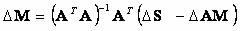
[0098] Embodiment 3: This embodiment is basically the same as Embodiment 1, and the special features are: see Figure 6 . System schematic diagram of the Mueller matrix of the optical system between any two points in this test method. The test is carried out in four steps. Step 1: Measure the Stokes parameter of the output polarization state of the polarization generator for the driving voltage ; Second: place the polarization generator at point A of the input terminal of the subsystem under test, and measure the polarization state of the output terminal of the system corresponding to the control voltage ;The third step: place the polarization generator at point B of the output end of the system under test, and measure the polarization state of the output end of the system when the corresponding control voltage . Step 4: Establish the following system equations:

[0099] ,in . The solution of the system equation is completed by the computer (6), and the require...


PUM


Abstract

The invention relates to a testing device for realizing Mueller matrix of an optical device based on a rotatable wave plate and a method. A testing system consists of a laser device, a polarization generator, a tested device, a polarization analyzer, a voltage controller and a computer. Light generated by the laser device enters the polarization generator, the polarization generator consists of a polarizer and the rotatable wave plate, the rotation angle of the wave plate is larger than 180 degrees, rotation of the wave plate is controlled by voltage, and the polarization generator generates different polarization state outputs under different control voltages. Light outputted by the polarization generator enters the tested device, light outputted by the tested device directly enters the polarization analyzer, and the polarization analyzer detects corresponding output polarization states of the polarization generator and corresponding Stokes parameters of output polarization states of the tested device when in different control voltages. Afterwards, a linear system equation among detected input and output polarization state parameters and Mueller matrix parameters of the tested device is built, the computer solves the system equation, and then 16 parameters of the Mueller matrix can be solved.

Description

technical field [0001] The invention relates to a Mueller matrix testing device and method based on a rotatable wave plate. It is a kind of Mueller matrix testing method for optical devices by combining a polarization generator composed of a rotatable wave plate and a polarization analyzer in an optical fiber system. Matrix testing apparatus and methods. Background technique [0002] In optical communication, sensing, and measurement systems, the polarization conversion characteristics of various photonic devices and subsystems directly affect the performance of the system. Therefore, detecting the polarization conversion characteristics of any part of the system or device in various optical systems is the key to achieving high performance. One of the keys to optical communication, optical sensing and measurement systems. [0003] In addition, in the research and manufacturing process in the field of material science, the polarization characteristics of most light-transmitt...

Claims


Application Information

Patent Timeline
Patent Type & Authority Applications(China)
IPC IPC(8): G01M11/02
Inventor 王春华李力黄肇明刘涛
Owner SHANGHAI UNIV
Why Eureka
Try Eureka