Directional emission fluorescence imaging detection device

A fluorescence imaging and detection device technology, which is applied in the direction of fluorescence/phosphorescence, material excitation analysis, etc., can solve the problems of inability to quickly locate the region of interest, expensive, expensive devices, etc., to achieve easy implementation and promotion, rapid positioning, The effect of simple structure

Inactive Publication Date: 2014-07-02
XIAMEN UNIV
View PDF5 Cites 0 Cited by
  • Summary
  • Abstract
  • Description
  • Claims
  • Application Information

AI Technical Summary

Problems solved by technology

The above-mentioned SPCDE imaging system based on the objective lens type mainly has the following deficiencies: 1, the device is expensive or has a complicated structure
The commercialized total internal reflection microscope is extremely expensive. In the self-made device, it is necessary to use a high numerical aperture objective lens or a parabolic element instead of the objective lens. Among them, the high numerical aperture objective lens is expensive, and the parabolic top element instead of the objective lens The parts are prepared by injection molding, the mold design and processing are difficult and require high precision, and the dyes with different emission wavelengths correspond to molds with different shapes and structures, so the preparation and operation are quite complicated
2. The imaging system based on the objective lens collects the emission signal through the objective lens, and the obtained spot area is small, so it can only image a small area of ​​the sample to be tested, and cannot quickly locate the area of ​​interest
3. The objective lens imaging system basically adopts the KR mode. Due to the participation of the evanescent field excitation, the energy of the excited fluorophore is enhanced, and strong excitation is likely to cause bleaching of the fluorophore or damage to the sample.
Therefore, it is difficult to realize and promote the SPCDE imaging device based on the objective lens in ordinary laboratories, which limits the promotion and application of this imaging technology.

Method used


Image

  • Directional emission fluorescence imaging detection device
  • Directional emission fluorescence imaging detection device
  • Directional emission fluorescence imaging detection device

Examples


Embodiment Construction

[0028] The present invention will be further described below in conjunction with the embodiments and accompanying drawings.

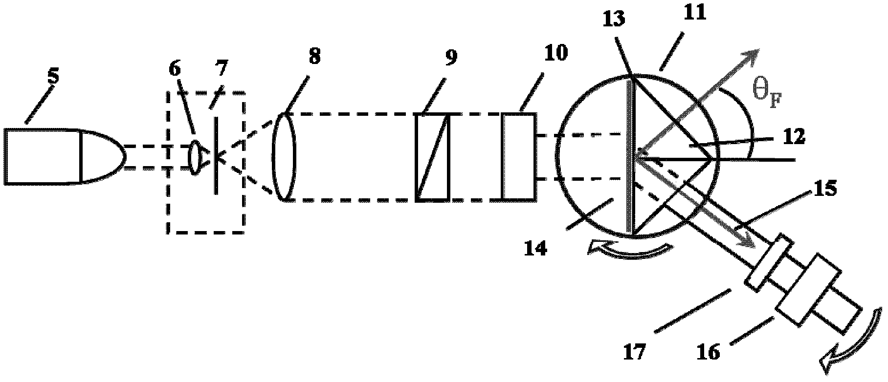
[0029] Such as image 3 As shown, the embodiment of the present invention is provided with a laser beam expander system, a sample system and a detection system.

[0030] The laser beam expander system is provided with a laser light source 5, a microscopic objective lens 6, a pinhole 7, a plano-convex lens 8, an attenuator 9 and a rectangular diaphragm 10; the excitation light emitted by the laser light source 5 passes through the microscopic objective lens 6, After the beam is expanded and collimated by the pinhole 7 and the plano-convex lens 8, it becomes a parallel beam, and the parallel beam passes through the attenuator 9 and the rectangular diaphragm 10 in sequence to obtain a rectangular spot.

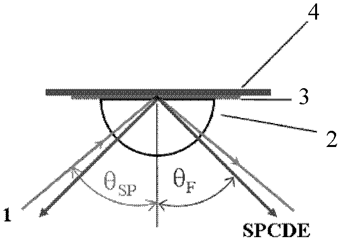
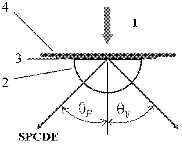
[0031] The sample system is provided with a rotary table 11, a sample holder, a prism 12 and an optical quartz substrate, the prism 12 is placed on the s...


PUM

PropertyMeasurementUnit
diameteraaaaaaaaaa

Abstract

The invention relates to a fluorescence imaging detection device, and particularly provides a directional emission fluorescence imaging detection device, which is provided with an optical laser beam-expanding system, a sample system and a detecting system, wherein the optical laser beam-expanding system is provided with a laser light source, a microobjective, a needle hole, a plano-convex lens, an attenuator and a rectangular diaphragm, the excitation light emitted by the laser light source sequentially passes by the microobjective, the needle hole and the plano-convex lens for beam expanding and collimation to form parallel light beams, and the parallel light beams sequentially pass by the attenuator and the diaphragm to obtain light spots; the sample system is provided with a rotating stage, a sample rack, a prism and an optical quartz substrate, the prism is placed on the sample rack and fixed at the center of the rotating stage, a nanoscale metallic film is arranged on the surface of the quartz substrate, a fluorescence sensing film is arranged on the surface of the metallic film, and solution is coated between the quartz substrate and the prism; and the detecting system is provided with a CCD rotating arm, a CCD receiver and an optical filter, the CCD rotating arm is fixed on the stage board of the rotating stage, the CCD rotating arm is connected onto the stage board of the rotating stage, and the CCD receiver used for collecting images and the optical filter are arranged on the CCD rotating arm.

Description

technical field [0001] The invention relates to a fluorescence imaging detection device, in particular to a prism-type surface plasmon coupling directional emission fluorescence imaging detection device. Background technique [0002] Due to the increasing application of fluorescence analysis technology in life science fields such as immune analysis, gene expression, drug screening, biosensing, and cell imaging, the research on new fluorescence technology and instruments has great significance and broad development prospects. Surface Plasmon Coupled Directional Emission (SPCDE) is a new fluorescence analysis method proposed recently. After the coupling of surface plasmons generated by free electrons, the SPCDE angle corresponding to the fluorescence emission wavelength (ie θ SPCDE ) into the prism matrix radiation. As a new fluorescence technology, SPCDE not only has the advantages of metal surface fluorescence such as enhanced fluorescence intensity, quantum yield and phot...

Claims


Application Information

Patent Timeline
Patent Type & Authority Patents(China)
IPC IPC(8): G01N21/64
Inventor 李耀群蔡伟鹏刘倩曹烁晖
Owner XIAMEN UNIV
Why Eureka
Try Eureka