Optical signal connection module

A technology for connecting modules and optical signals, applied in the field of optical signal connecting modules, can solve the problems of high cost, complex structure, complicated production procedures, etc., and achieve the effect of saving cost and reducing attenuation

Inactive Publication Date: 2012-07-04
PRIME OPTICAL FIBER
View PDF6 Cites 9 Cited by
  • Summary
  • Abstract
  • Description
  • Claims
  • Application Information

AI Technical Summary

Problems solved by technology

However, its structure is complex, not only the production procedures are complicated, but also the cost is high, and it is not conducive to the automatic plug-in use of automatic machines

Method used


Image

  • Optical signal connection module
  • Optical signal connection module
  • Optical signal connection module

Examples


Embodiment Construction

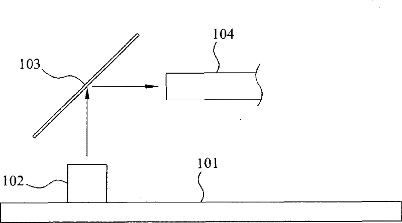
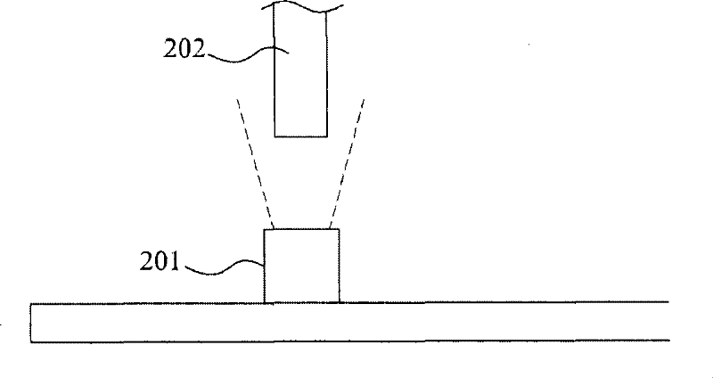
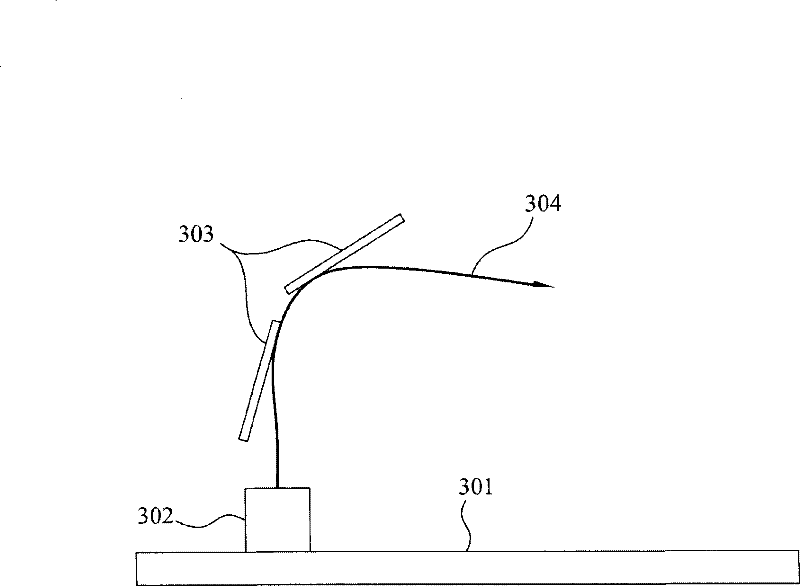
[0042] image 3 Shown is a schematic diagram of the design concept of the optical signal connection module of the present invention. In order to reduce the degradation of the optical signal intensity of the light transmission path of the point light source due to the Gaussian distribution, the optical signal connection module of the present invention uses a set of optical fiber guide grooves on the guide groove plate 303 to guide the optical fiber 304 to the optical signal of the circuit board 301 At the transceiving area 302, at least one point light source or a receiver is provided in the optical signal transceiving area 302. For example, the optical fiber 304 is positioned directly above the point light source so that the cut surface of the optical fiber can directly face the point light source. Wherein, the dynamic fatigue value of the optical fiber 304 (Dynamic Fatigue value) ND>20, a preferred embodiment is ND>25. It’s worth noting that compared to figure 1 According to t...


PUM


Abstract

The invention provides an optical signal connection module. Primarily, at least one guide hole, at least one group of optical fiber guide grooves and an observation window are formed on a shell of the module; the observation window is arranged at a position opposite to the end point of the optical fiber guide grooves in the shell; the guide hole is positioned on a side wall of the shell for feeding an optical fiber into the shell; and the optical fiber guide grooves are formed in the shell to guide the optical fiber to bend at a large angle, so that the front edge of the optical fiber reaches the position of the observation window. The optical signal connection module can be placed to cover an optical signal transmitting and receiving region; and a point light source or a receiver is at least arranged in the optical signal transmitting and receiving region, so that a signal of the optical signal transmitting and receiving region can be transmitted between the region and exterior. Through the optical signal connection module, the attenuation of intensity of the optical signal can be reduced, so that the optical fiber does not rock, the problem of fixation of the optical fiber is not concerned, the space of a circuit board is not occupied, meanwhile, more cost is saved.

Description

Technical field [0001] The invention relates to an optical signal connection module, in particular to a bidirectional embedded optical fiber connection technology (Bidirectional Embedded S-Bend Technology, BEST). Background technique [0002] Compared with traditional electrical signals, light has long replaced traditional electrical signals due to its superior physical characteristics such as large bandwidth, low loss, high security, immunity from electromagnetic fields or electromagnetic radiation, etc. Signal becomes the first choice for data signal transmission. Optical fiber is the medium used to transmit optical signals. Optical fiber communication is suitable for long-distance communication because of its low signal distortion, and also greatly reduces the cost of transmission. Furthermore, the optical fiber is light and flexible, so it is easy to be assembled into bundles, saving pipeline space and improving the economic benefits of space configuration. Therefore, with...

Claims


Application Information

Patent Timeline
Patent Type & Authority Applications(China)
IPC IPC(8): G02B6/42
Inventor 蒋念祖胡志强
Owner PRIME OPTICAL FIBER
Why Eureka
Try Eureka