
Electronic seal

An electronic seal and integrated technology, which is applied in the direction of record carriers, instruments, computer components, etc. used by machines, can solve the problems that the cost cannot be further reduced and the efficiency of electronic seals is low.

Active Publication Date: 2012-07-04
陈志权
View PDF5 Cites 9 Cited by
  • Summary
  • Abstract
  • Description
  • Claims
  • Application Information

AI Technical Summary

Problems solved by technology

[0005] The purpose of the present invention is to provide an electronic seal to solve the problem in the prior a

Method used


Image

  • Electronic seal
  • Electronic seal
  • Electronic seal

Examples


Embodiment Construction

[0052] In order to further explain the technical solution of the present invention, the present invention will be described in detail below through specific examples.

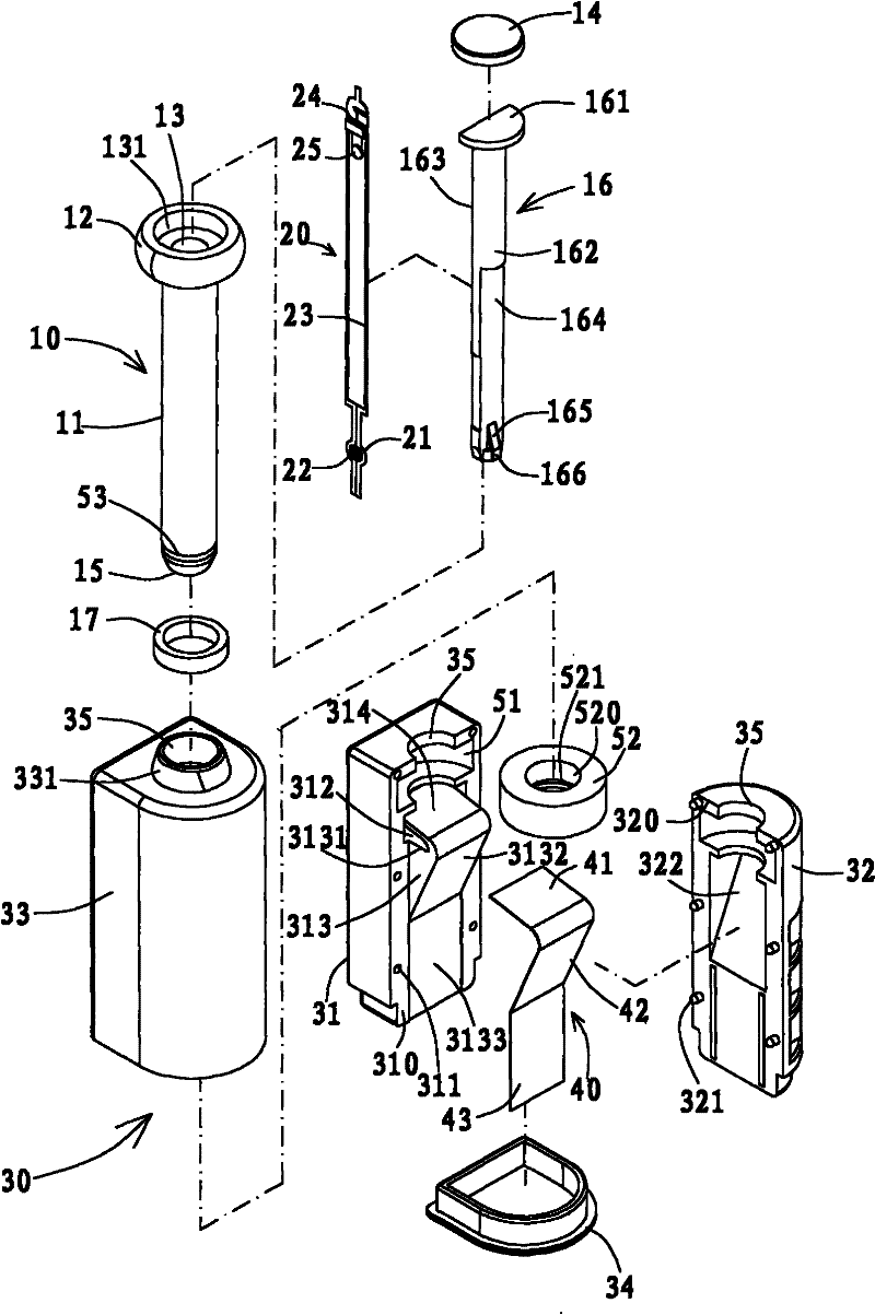
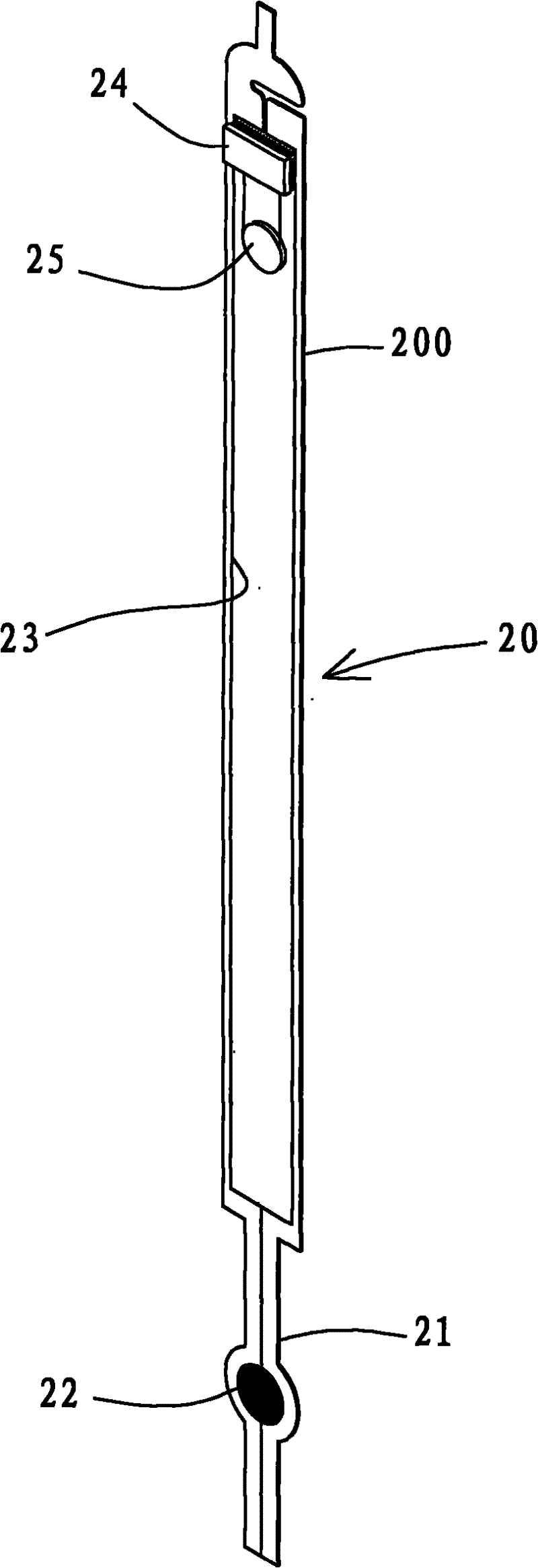
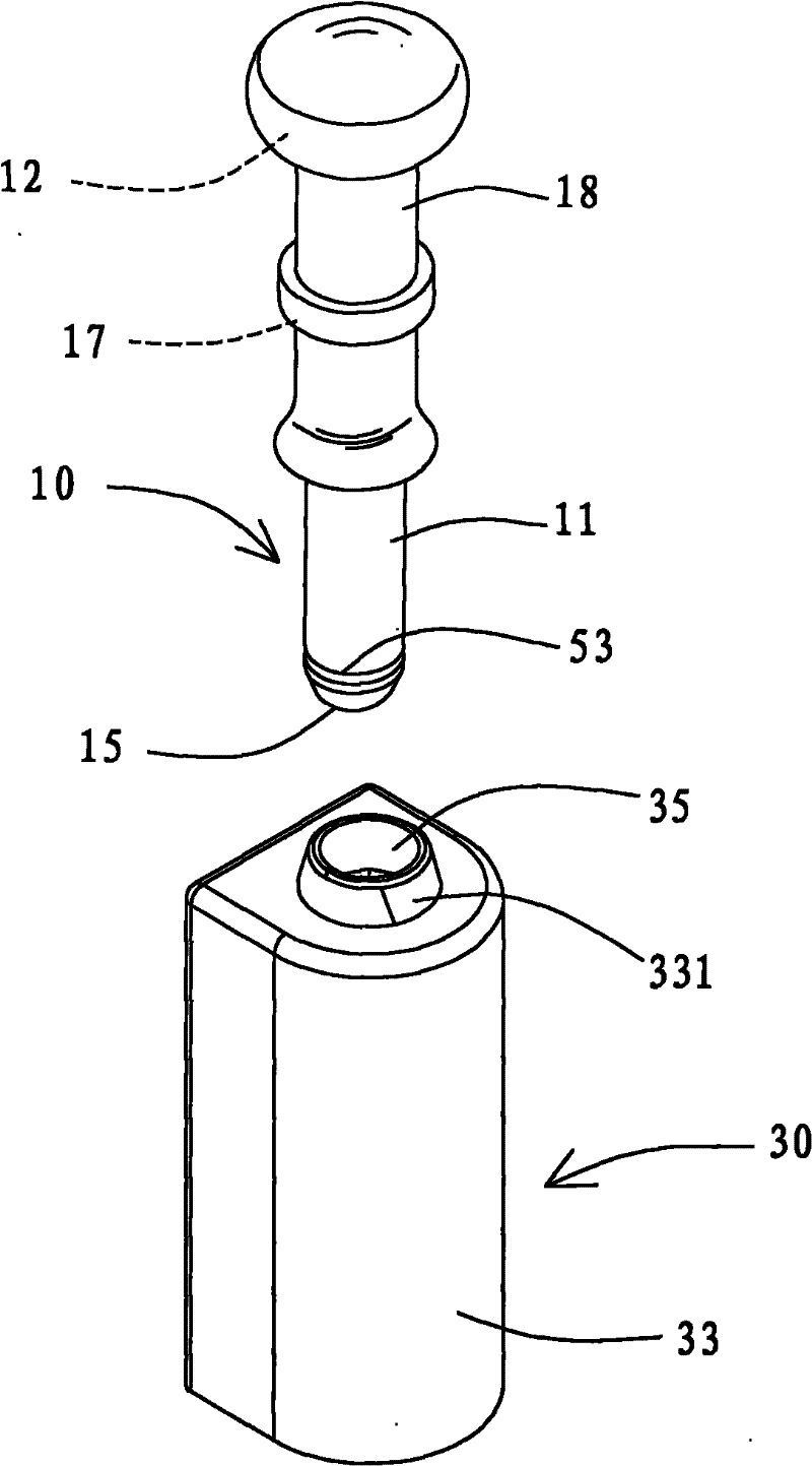
[0053] see Figure 1 to Figure 6 As shown, the present invention at least includes:

[0054] A plug 10, which has a shaft 11, a cap head 12 radially outwardly expanding at the top of the shaft 11, a cavity 13 axially penetrating through the shaft 11 and the cap head 12, the top edge of the cavity 13 There is a countersunk hole 131 that expands radially outwards, so that it can be closed by a cover body 14. As for the bottom edge of the shaft 11, a taper portion 15 that tapers downwards in the outer diameter is formed. The rod 16 is fixed, and the inner rod 16 has a head end 161 limited to the countersunk hole 131 and a shaft portion 162 passing through the bottom end of the containing hole 13. The head end 161 and the shaft portion 162 have a first cut through the top and bottom plane 163, and the lower half ...


PUM


Abstract

The invention discloses an electronic seal, which comprises a pin, a pin seat, an antenna and an RFID (radio frequency identification) chip, wherein the pin can penetrate into the pin seat but cannot retreat from the pin seat, the antenna is mounted on the pin seat, and the RFID chip can be matched with the antenna. The pin seat is provided with a shaft hole axially recessed and a demoulding groove radially communicated with the bottom end of the shaft hole, the pin can penetrate into the shaft hole, a spring sheet is integrally formed in the demoulding groove, the top surface of the spring sheet is positioned below the shaft hole, the antenna is combined to the pin seat and the top surface of the spring sheet by the aid of a pasting layer, so that the antenna and the RFID chip can be in stable electric connection by the aid of the restoring force of the spring sheet after the pin penetrates into the shaft hole but cannot retreat from the shaft hole, the electric connection can be cut off, and a recognition host mounted in a customhouse can achieve the functions of rapid recognition and container management. As the spring sheet is integrally formed in the pin seat, assembly efficiency can be greatly improved, and production cost can be greatly reduced.

Description

technical field [0001] The invention relates to an electronic seal that can be assembled modularly, especially a special technology that can ensure that the plug still has a stable electrical connection after it is inserted into the plug seat without installing additional springs. Background technique [0002] The previous technology is just as in the "electronic seal" disclosed by Taiwan No. I292007 Figure 8 , Figure 10 and Figure 13, the fixing seat, buckle and tail are all made of conductive metal, and the fixing seat presses the second antenna, so that the plug cannot retreat after the plug seat is inserted , so that the bottom end of the bolt rod can overcome the elastic force of the elastic component and maintain the state of pressing the sliding seat to form the electrical connection between the bolt rod, the radio frequency identification chip, the first antenna and the second antenna, so that the radio frequency identification chip can pass through the first , two ...

Claims


Application Information

Patent Timeline
IPC IPC(8): G06K19/07
Inventor 陈志权
Owner 陈志权
Learn More