Leakage protection plug

A leakage protection plug and resistor technology, applied in circuits, electrical components, coupling devices, etc., can solve the problems of leakage protection plug tripping, failure to ensure electricity safety, and failure to work normally.

Active Publication Date: 2012-07-04
佛山市新基德电子厂有限公司
View PDF6 Cites 20 Cited by
  • Summary
  • Abstract
  • Description
  • Claims
  • Application Information

AI Technical Summary

Problems solved by technology

figure 1 Shown is an existing optocoupler 100, its input end is composed of a neon lamp 100-1 to form a light-emitting element, and its output end is composed of a phototransistor 100-2 to form a light-receiving element, from the characteristics of the neon lamp 100-1 we can know , the starting voltage of the neon lamp 100-1 usually needs to be about 85V or above. It can be seen from this that when the leakage protection plug uses this kind of photocoupler 100 to detect the voltage between the ground wire and the neutral wire , this

Method used


Image

  • Leakage protection plug
  • Leakage protection plug
  • Leakage protection plug

Examples


Embodiment 1

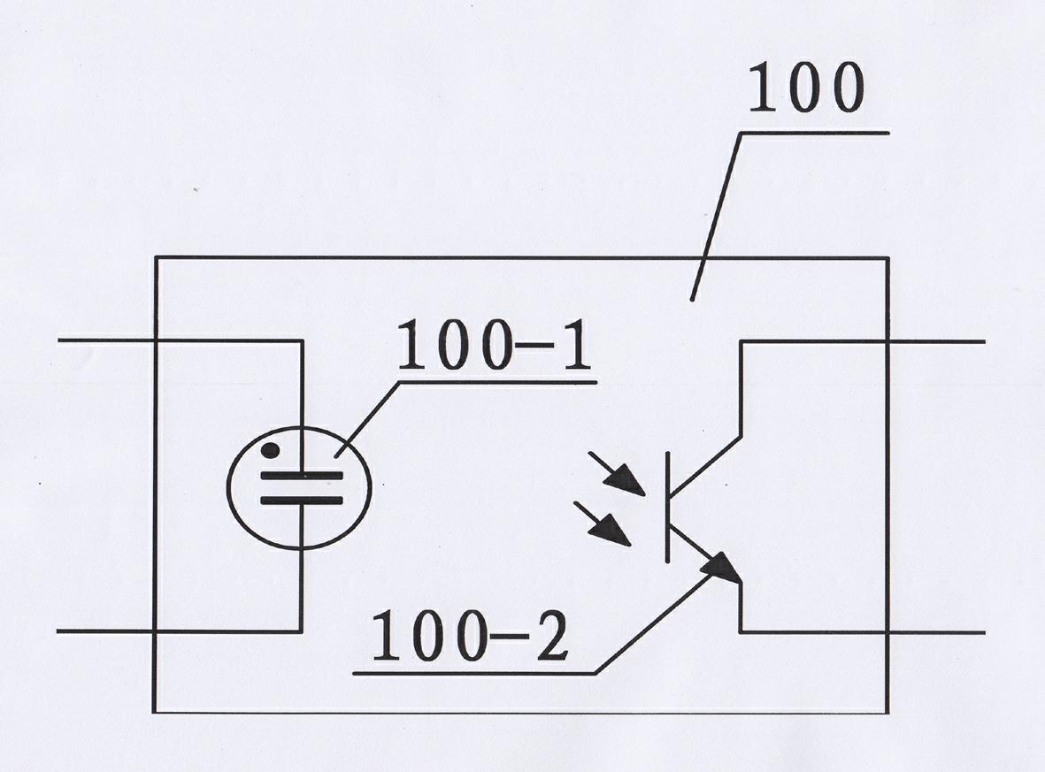
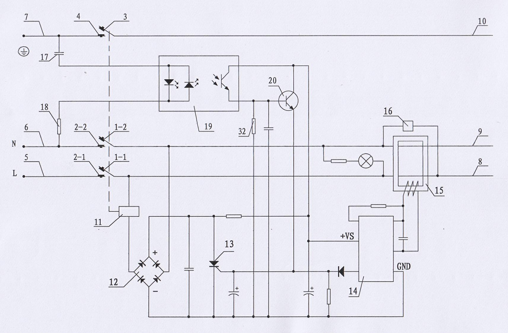
[0046] see figure 2 As shown, a leakage protection plug is mainly composed of a shell and a plug, a phase wire 5 and a neutral wire 6 and a ground wire 7 at the power supply end, a phase wire 8 and a neutral wire 9 and a ground wire 10 at the load end, a zero-sequence current transformer 15, Test circuit 16, electromagnetic tripping and locking device, the electromagnetic tripping and locking device includes electromagnetic coil 11 and its drive circuit, phase line contacts 1-1 and 2-1, neutral line contacts 1-2 and 2 -2. Ground wire contacts 3 and 4, a spring, a reset push rod, a first resistance-capacitance element 17, a second resistance-capacity element 18, a photocoupler 19, and a trigger circuit. Between the ground wire 7 and the neutral wire 6, a detection circuit formed by connecting one input end of the first resistance-capacitance element 17, one input end of the photocoupler 19 and the other input end, and the second resistance-capacity element 18 in series, the ph...

Embodiment 2

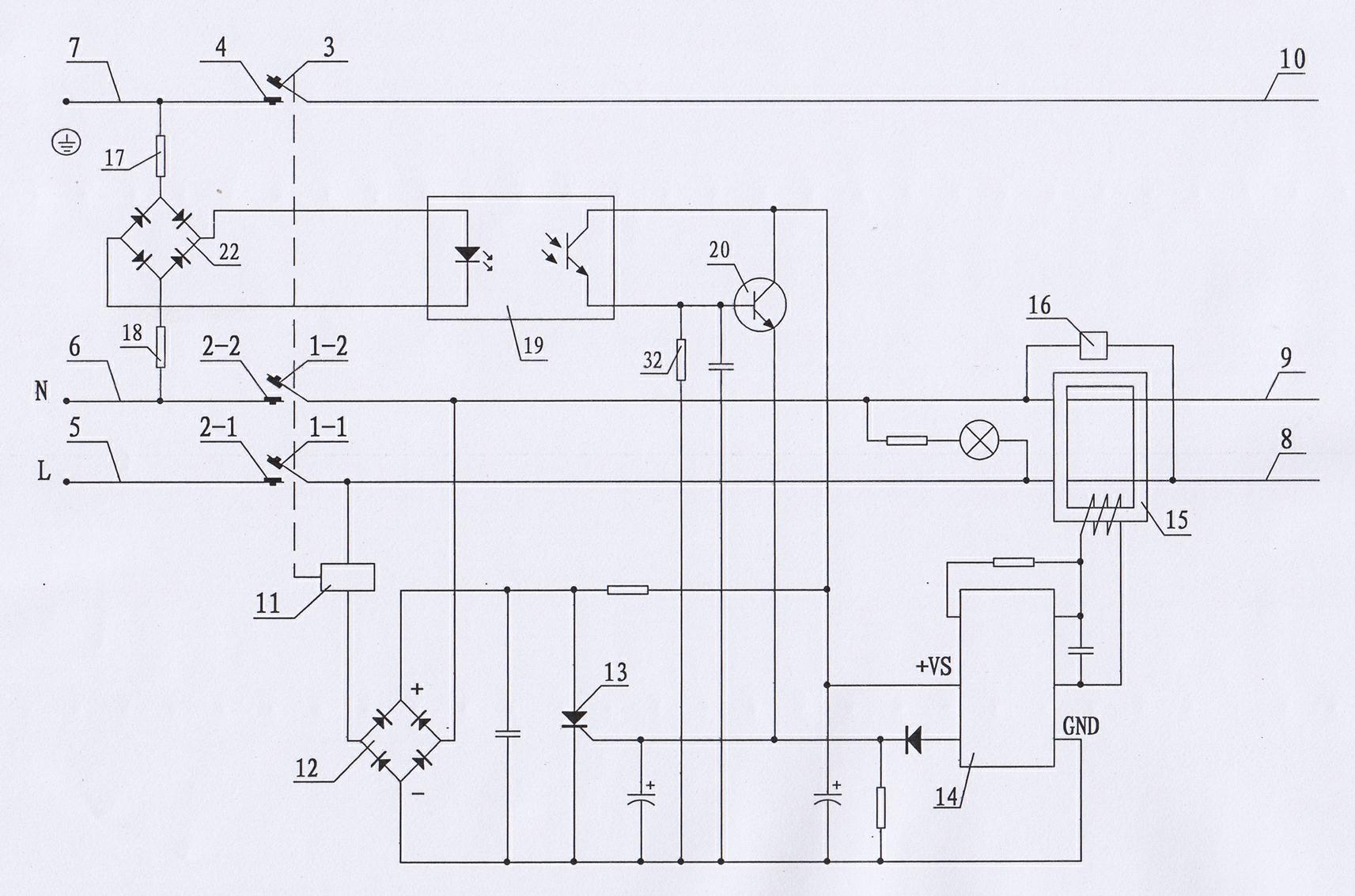
[0057] see image 3 As shown, compared with the first embodiment, the second rectification circuit 22 is added in this embodiment.

[0058] In this embodiment, it is composed of the first resistance-capacitance element 17, one input end and the other input end of the second rectification circuit 22, one input end and the other input end of the photocoupler 19, and the second resistance-capacitance element 18 The detection circuit is connected between the ground wire 7 and the neutral wire 6 at the power supply end, and one output end and the other output end of the second rectification circuit 22 are respectively connected to an input end and the other input end of the photocoupler 19 .

[0059] In this embodiment, the first resistance-capacitance element 17 is a resistor, and a capacitor or a combination of a resistor and a capacitor can also be used; the second resistance-capacity element 18 is a resistor, and a capacitor or a combination of a resistor and a capacitor can al...

Embodiment 3

[0065] see Figure 4 As shown, compared with the second embodiment, the present embodiment adds the first diode 23 and cancels the second rectifying circuit 22 in the second embodiment.

[0066] In this embodiment, the first diode 23, the first resistance-capacitance element 17, one input end and the other input end of the photocoupler 19, and the second resistance-capacitance element 18 form a detection loop connected to the ground wire 7 and the power supply end. Between the neutral line 6, one end of the first diode 23 is connected to the ground wire 7, the other end of the first diode 23 is connected to one end of the first resistance-capacitance element 17, and the other end of the first resistance-capacity element 17 is connected to the photocoupler 19. One input end is connected, the other input end of the photocoupler 19 is connected to one end of the second resistance-capacitance element 18 , and the other end of the second resistance-capacity element 18 is connected ...


PUM


Abstract

The invention discloses a leakage protection plug. Electrical shock hazards caused by failures of electric appliances as well as accidental electrification of a ground wire can be prevented. A first resistance-capacitance element, a second resistance-capacitance element, a photoelectric coupler and a trigger circuit are also arranged on the leakage protection plug, wherein a detection loop which is formed by connecting the first resistance-capacitance element, one input end and the other input end of the photoelectric coupler, and the second resistance-capacitance element in series is connected between the ground wire and a zero wire; a signal output by the photoelectric coupler is sent to the input end of the trigger circuit; and the output end of the trigger circuit is connected with the control end of a driving circuit of an electromagnetic coil.

Description

technical field [0001] The invention relates to the technical field of electricity safety protection, in particular to an electric leakage protection plug. Background technique [0002] Chinese patent document CN1142618C discloses a leakage protection plug. The leakage protection plug is not only equipped with a zero-sequence current transformer through which both the phase line and the neutral line pass, but also has a ground wire live detection sensor through which the ground wire passes. Therefore, it can not only detect whether there is residual current between the phase line and the neutral line at the load end, but when there is a residual current between the phase line and the neutral line and reaches the preset threshold value (for example: 10mA), it will be within 0.1S It trips immediately to cut off the phase wire, neutral wire and ground wire; and when the ground wire is accidentally electrified due to an abnormal grounding protection system, it can also detect wh...

Claims


Application Information

Patent Timeline
IPC IPC(8): H01R13/66H01R13/70H01R13/717
Inventor 刘睿刚
Owner 佛山市新基德电子厂有限公司
Why Eureka
Try Eureka