Compression joint clamp of steel-cored aluminum strand

A steel-cored aluminum stranded wire and clamp technology, applied in the direction of cable joints, etc., can solve problems such as easy heating, potential safety hazards, and reduced cross-section of the outer surface of the flow, achieving obvious effects, high connection reliability, and reduced scrap rate. Effect

Active Publication Date: 2012-07-04
STATE GRID ZHEJIANG ELECTRIC POWER CO LTD QUZHOU POWER SUPPLY CO +2
View PDF4 Cites 8 Cited by
  • Summary
  • Abstract
  • Description
  • Claims
  • Application Information

AI Technical Summary

Problems solved by technology

[0002] When the steel-cored aluminum stranded wire is crimped with the aluminum tube at its connector, since the elastic modulus of the outer layer of the aluminum stranded wire is smaller than that of the inner steel core, the elongation of the aluminum stranded wire after the aluminum tube is crimped is larger than that of the steel core As a result, there is a relative displacement between the aluminum strands, the steel core, and the inner and outer layers of the aluminum strands; moreover, since the crimping part gradually transitions from the middle of the aluminum tube to the end, the extension and deformation of the aluminum strands are towards the aluminum tube. In the end, the aluminum cored aluminum stranded wire will have loose strands and expansion near the aluminum tube orifice, and this phenomenon will lead to a difference in force between the inner and outer layers of the aluminum strand, thereby reducing the mechanical strength of the steel cored aluminum stranded wire , so that the cross-section of the outer surface of the flow is reduced, the resistance is increased, and it is easy to generate heat. There are certain safety hazards, and the appearance quality is also poor. It is difficult to meet the quality requirements of the power acceptance connection nozzle specification.

Method used


Image

  • Compression joint clamp of steel-cored aluminum strand
  • Compression joint clamp of steel-cored aluminum strand

Examples


Embodiment Construction

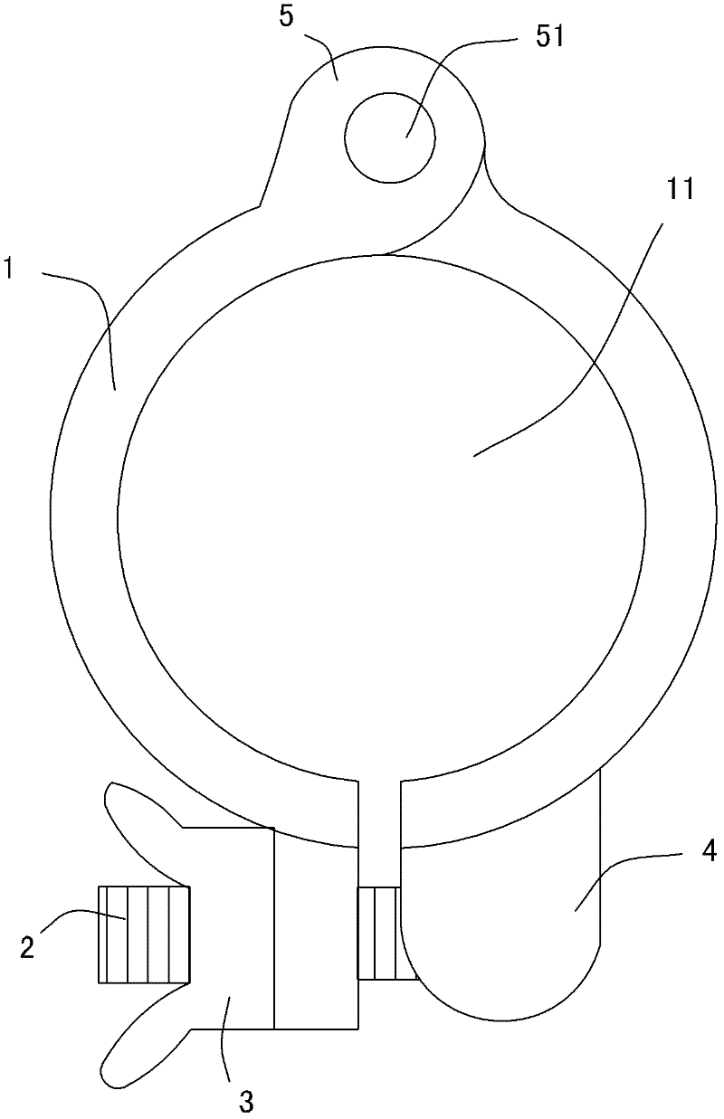
[0010] see figure 1 . The two semi-annular hoop pieces 1 that are separated are riveted together by the hinge shaft 51 . In specific implementation, lugs 5 can be provided on the hoop at the riveted part of the hinge shaft 1 , which not only facilitates the riveting of the hinge shaft 51 , but also does not affect the inner circle 11 formed by the two hoop sheets 1 to receive the steel core aluminum stranded wire. A connecting seat 4 is respectively provided on the free ends of the two half-ring hoop pieces 1 , and the shape of the connecting seat only needs to be able to form a whole of the two connecting seats 4 through a fastener. In specific implementation, the fastener can be a bolt 2 and a wing nut 3, so that one end of the bolt 2 is positioned in the screw hole of one side connecting seat 4, and the wing nut 3 is screwed on the bolt 2 at the other end. When in use, as long as the wing nut 3 is tightened, the free ends of the two half-ring hoop pieces 1 will be combin...


PUM


Abstract

Provided is a compression joint clamp of a steel-cored aluminum strand. Two split semi-ring clamp sheets are riveted through a hinge shaft, a connection seat is respectively arranged at the free-ends of the two semi-ring clamp sheets, and the two connection seats form a whole through a fastener. When the compression joint clamp is used, an aluminum strand arranged outside an opening of an aluminum pipe extends to the position where transformation quantity is easy to gather to achieve the aim of preventing aluminum strand transformation quantity generated by the compression joint aluminum pipe from extending to an aluminum-strand wire, so that the transformation quantity can be digested on the steel-cored aluminum strand in the aluminum pipe. Under the effect of compression joint force, transformation of the steel-cored aluminum strand in the aluminum pipe cannot affect mechanical strength of the steel-cored aluminum strand, the transformation enables the steel-cored aluminum strand and the inner wall of the aluminum pipe to generate stronger combining force, and connection reliability is higher. Practice proves that the clamp effectively reduces scrappage of the wire, strand broken rate and expansion rate of the wire are reduced to 3% from 40%, and the effect is obvious.

Description

【Technical field】 [0001] The invention belongs to a crimping clamp for assisting the connection of a steel-cored aluminum stranded wire and an aluminum pipe in electric construction. 【technical background】 [0002] When the steel core aluminum stranded wire is crimped with the aluminum tube, since the elastic modulus of the outer aluminum stranded wire is smaller than that of the inner steel core, the extension of the aluminum stranded wire after the aluminum tube is crimped is larger than that of the steel core. Therefore, the relative displacement between the aluminum strand and the steel core and the inner and outer layers of the aluminum strand occurs; in addition, since the crimping part gradually transitions from the middle of the aluminum tube to the end, the extension deformation of the aluminum strand is directed toward the aluminum tube. The tube orifice of the steel core is concentrated, and finally the steel-cored aluminum stranded wire will appear scattered and ...

Claims


Application Information

Patent Timeline
Patent Type & Authority Applications(China)
IPC IPC(8): H02G15/08
Inventor 徐建华洪建军李为汪列红孙爱民陶礼兵
Owner STATE GRID ZHEJIANG ELECTRIC POWER CO LTD QUZHOU POWER SUPPLY CO
Why Eureka
Try Eureka