
Ink gun manufacturing method, ink gun and printing equipment

A manufacturing method and technology for an inkjet head, which are applied in the field of inkjet head and printing equipment, and inkjet head manufacturing, can solve the problems of increasing the manufacturing cost, affecting the mechanical strength and performance of the substrate, and thinning the side wall, so as to improve the yield of finished products. , The effect of improving manufacturing efficiency and manufacturing accuracy

Active Publication Date: 2015-03-18
ZHUHAI SAILNER 3D TECH CO LTD
View PDF5 Cites 3 Cited by
  • Summary
  • Abstract
  • Description
  • Claims
  • Application Information

AI Technical Summary

Problems solved by technology

[0004] The invention provides a method for manufacturing an inkjet head, which is used to solve the problem of increasing the number of pressure chambers in the prior art and causing the sidewalls to become thinner, thereby affecting the mechanical strength and performance of the substrate, and the sidewalls between the pressure chambers are easily damaged The problem of increasing manufacturing costs

Method used

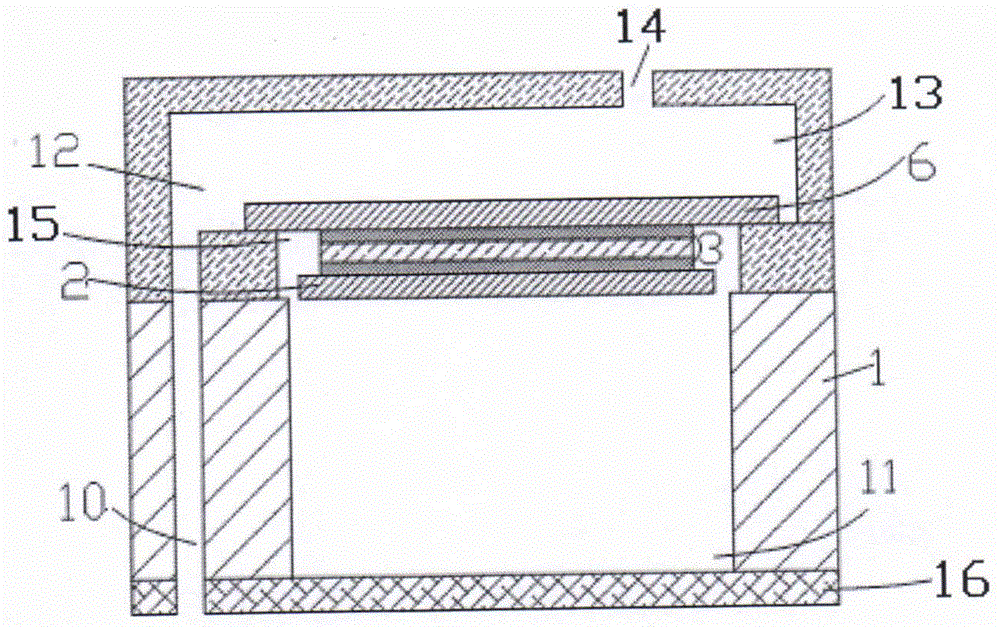

Image

  • Ink gun manufacturing method, ink gun and printing equipment
  • Ink gun manufacturing method, ink gun and printing equipment
  • Ink gun manufacturing method, ink gun and printing equipment

Examples


Embodiment Construction

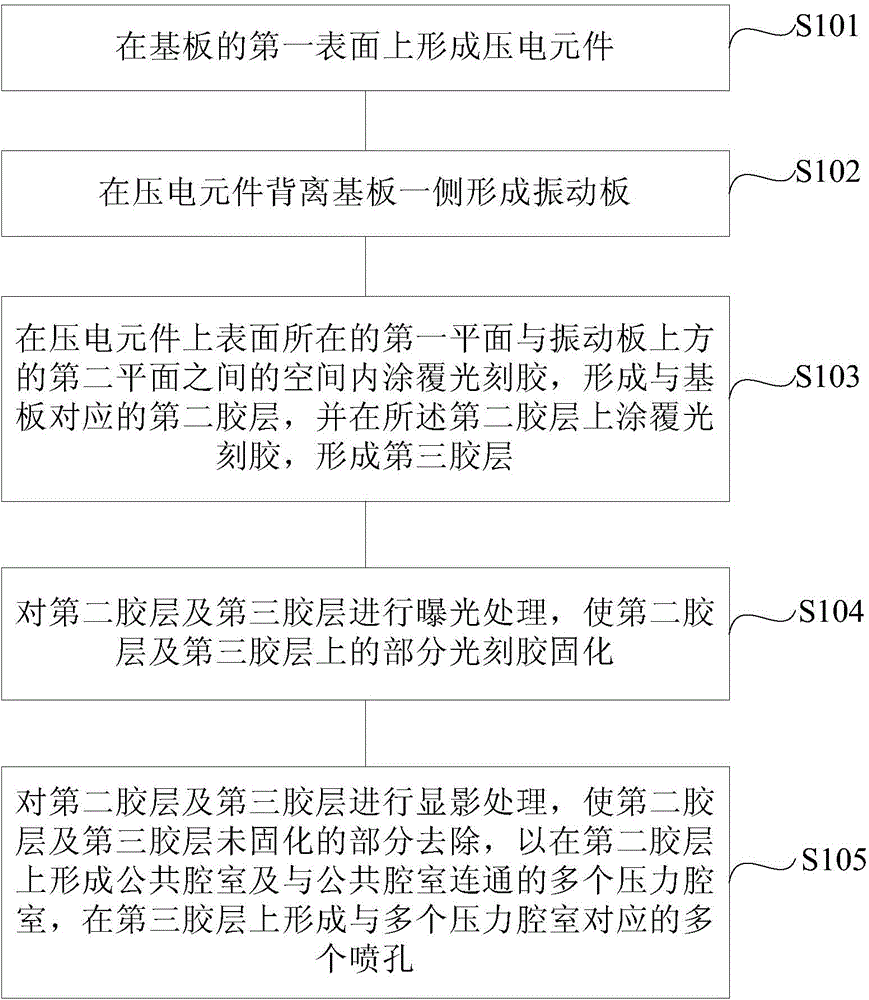
[0033] Embodiment 1 of the present invention provides a method for manufacturing an inkjet head, specifically as figure 2 As shown, the method includes the following steps:

[0034] S101, forming a piezoelectric element on the first surface of the substrate;

[0035] In this embodiment, the formation of the piezoelectric element specifically includes: sequentially forming a lower electrode layer on the first surface of the substrate by sputtering, forming a piezoelectric layer on the lower electrode layer by a sol-gel method, and The upper electrode layer is formed by sputtering.

[0036] S102, forming a vibrating plate on a side of the piezoelectric element away from the substrate;

[0037] In this embodiment, the vibrating plate can be formed by low pressure chemical vapor deposition or plasma enhanced chemical vapor deposition.

[0038] S103. Coating photoresist in the space between the first plane where the upper surface of the piezoelectric element is located and the ...


PUM


Abstract

The invention provides an ink gun manufacturing method, an ink gun and printing equipment. The ink gun manufacturing method comprises the following steps: forming a piezoelectric element on a first surface of a base plate; forming a vibration plate on one side, opposite to the base plate, of the piezoelectric element; forming a second adhesive layer inside a space between a first plane with the upper surface of the piezoelectric element and a second surface on the vibration plate, and forming a third adhesive layer on the second adhesive layer; and exposing and developing the second adhesive layer and the third adhesive layer, curing part of photoresist on the second adhesive layer and the second adhesive layer, removing uncured parts, forming a public chamber and a pressure chamber on the second adhesive layer, and forming a plurality of ejection holes in the third adhesive layer. By adopting the ink gun manufacturing method, the ink gun and the printing equipment provided by the invention, not only are the manufacturing efficiency and the manufacturing precision improved, but also the mechanical strength and the property of a substrate are not affected even when the sizes of the pressure chamber and the side walls are reduced in machining, and the finished product rate of the ink gun is increased in the production process.

Description

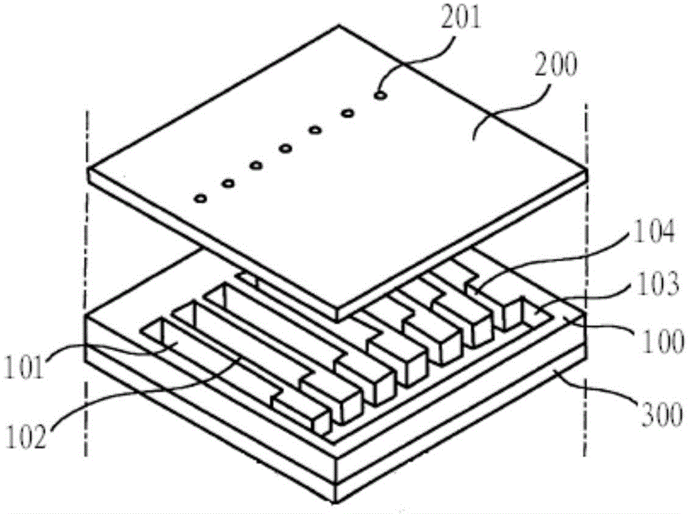
technical field [0001] The invention relates to printer manufacturing technology, in particular to an inkjet head manufacturing method, inkjet head and printing equipment. Background technique [0002] In the existing technology, such as figure 1 As shown, the inkjet head structure in the printing device generally includes a substrate 100, and a plurality of pressure chambers 101 and a common chamber 103 are formed on one side of the substrate 100 through an etching process, and the plurality of pressure chambers 101 pass through the side wall 102 Separated, the common chamber 103 communicates with a plurality of pressure chambers 101 through the supply port 104, so that each pressure chamber 101 communicates with each other and supplies ink through the common chamber 103, and one side of each pressure chamber 101 is provided with On the other side of the orifice plate 200, a vibrating plate 300 and a piezoelectric element (not shown in the figure) are arranged. During prin...

Claims


Application Information

Patent Timeline
Patent Type & Authority Applications(China)
IPC IPC(8): B41J2/16
Inventor 李越
Owner ZHUHAI SAILNER 3D TECH CO LTD
Learn More