
Permanent magnet motor and manufacturing method thereof

A permanent magnet and magnet technology, which is applied to the field of permanent magnet motors and their manufacturing, can solve the problems of complicated manufacturing process, increased cost, difficult removal operations, etc., and achieves the effect of reducing the work burden

Active Publication Date: 2016-01-06
HITACHI IND EQUIP SYST CO LTD
View PDF7 Cites 0 Cited by
  • Summary
  • Abstract
  • Description
  • Claims
  • Application Information

AI Technical Summary

Problems solved by technology

[0011] However, such spilled adhesive is essentially useless, and contact with workers or other products during the manufacturing process will deteriorate the quality, so it is desirable to keep it to a minimum.
[0012] On the other hand, if the adhesive is too small and the adhesive does not overflow around the magnet, it cannot be confirmed whether the adhesive is evenly filled between the bottom surface of the magnet and the bottom of the groove formed in the rotor core. The application has to be carried out in such a way that the adhesive overflows to some extent, for this reason, after the magnet 1 is pressed in, the process of removing and cleaning the adhesive that has flowed out without any control in the entire area of ​​its periphery is essential
In particular, when the spilled adhesive is cured, it is difficult to remove it, the manufacturing process becomes complicated, and it becomes a cause of cost increase.

Method used


Image

  • Permanent magnet motor and manufacturing method thereof
  • Permanent magnet motor and manufacturing method thereof
  • Permanent magnet motor and manufacturing method thereof

Examples


Embodiment

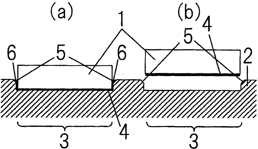
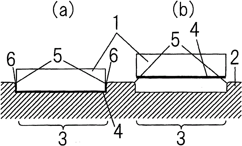
[0035] Figure 1 to Figure 10 The first to sixth embodiments showing the adhesive structure of the present invention, and the one showing the conventional adhesive structure Figure 11 Similarly, (a) in the drawings shows the state where the magnet 1 is bonded to the rotor core 2, and (b) shows the state before the magnet 1 is bonded to the magnet groove portion 3 of the rotor core 2. Likewise, after applying the adhesive 4 in a predetermined amount, the magnet 1 is pressed in from above.

[0036] exist figure 1 In the first embodiment shown, the magnet 1 is in the shape of a flat plate, and the bottom surface of the magnet groove 3 of the rotor core 2 is coated with an adhesive having a certain viscosity such as synthetic rubber or epoxy. After compounding 4, the magnet 1 is pressed into the magnet groove 3 to be bonded.

[0037] In this first embodiment, a tapered portion 5 is provided on the upper end corners of the left and right side walls of the magnet groove portion ...


PUM


Abstract

PROBLEM TO BE SOLVED: To provide a function for confirming that an adhesive agent is filled uniformly between a permanent magnet and a rotor core over the whole area with ease and with certainty when adhering the permanent magnet to the rotor core in a permanent magnet motor. SOLUTION: In a permanent magnet motor, a groove matched to a shape of a permanent magnet is formed to an electromagnetic steel plate constituting a rotor core. An adhesive agent reservoir recessed part to which an adhesive agent flowing out from between bottom surfaces of both parties via a gap between a side wall of the groove and a side wall of the permanent magnet is introduced when the permanent magnet is pushed in the groove to be adhered by the adhesive agent applied between the bottom surfaces of both parties, is formed at an upper end of the side wall of the groove. The quantity of the adhesive agent stored in the recessed part can be visibly recognized to confirm an application state of the adhesive agent. COPYRIGHT: (C)2012,JPO&INPIT

Description

technical field [0001] The invention relates to a permanent magnet motor and a manufacturing method thereof, in particular to a bonding technique of a magnet to a rotor core. Background technique [0002] Usually, in such a permanent magnet motor, the magnet bonding surface formed on the outer peripheral surface or the inner peripheral surface of the rotor core formed by laminating electromagnetic steel sheets has the same width as the magnet and a depth that does not affect the magnetic properties. A plurality of grooves whose depth is one-tenth of the thickness of the magnet is provided, and an adhesive is coated between the bottom surface of the groove and the bottom surface of the magnet, and the magnet is positioned in the groove to form a structure bonded by pushing. [0003] In this way, the following Patent Documents 1 and 2 are cited as techniques for attaching magnets to the outer surface of the rotor core with an adhesive. [0004] Patent Document 1: Japanese Pat...

Claims


Application Information

Patent Timeline
IPC IPC(8): H02K1/27H02K15/03
Inventor 泽田享兵税所亮平山崎政英
Owner HITACHI IND EQUIP SYST CO LTD
Learn More