Fully-automatic gluing equipment suitable for various parts

A fully automatic, parts-based technology, applied in coatings, devices for coating liquid on the surface, etc., to achieve high production efficiency, good versatility, and uniform glue coating

Active Publication Date: 2012-07-11
DALIAN HUAGONG INNOVATION TECH
View PDF3 Cites 33 Cited by
  • Summary
  • Abstract
  • Description
  • Claims
  • Application Information

AI Technical Summary

Problems solved by technology

[0003] In order to solve the problem that the existing cylindrical, circular, conical, truncated truncated and truncated truncated ring parts cannot be fully automatic glued on one piece of equipment, the present invention further provides a highly versatile Fully automatic gluing equipment suitable for various parts (cylindrical, circular, conical, conical, and conical ring parts)

Method used


Image

  • Fully-automatic gluing equipment suitable for various parts
  • Fully-automatic gluing equipment suitable for various parts
  • Fully-automatic gluing equipment suitable for various parts

Examples


specific Embodiment approach 1

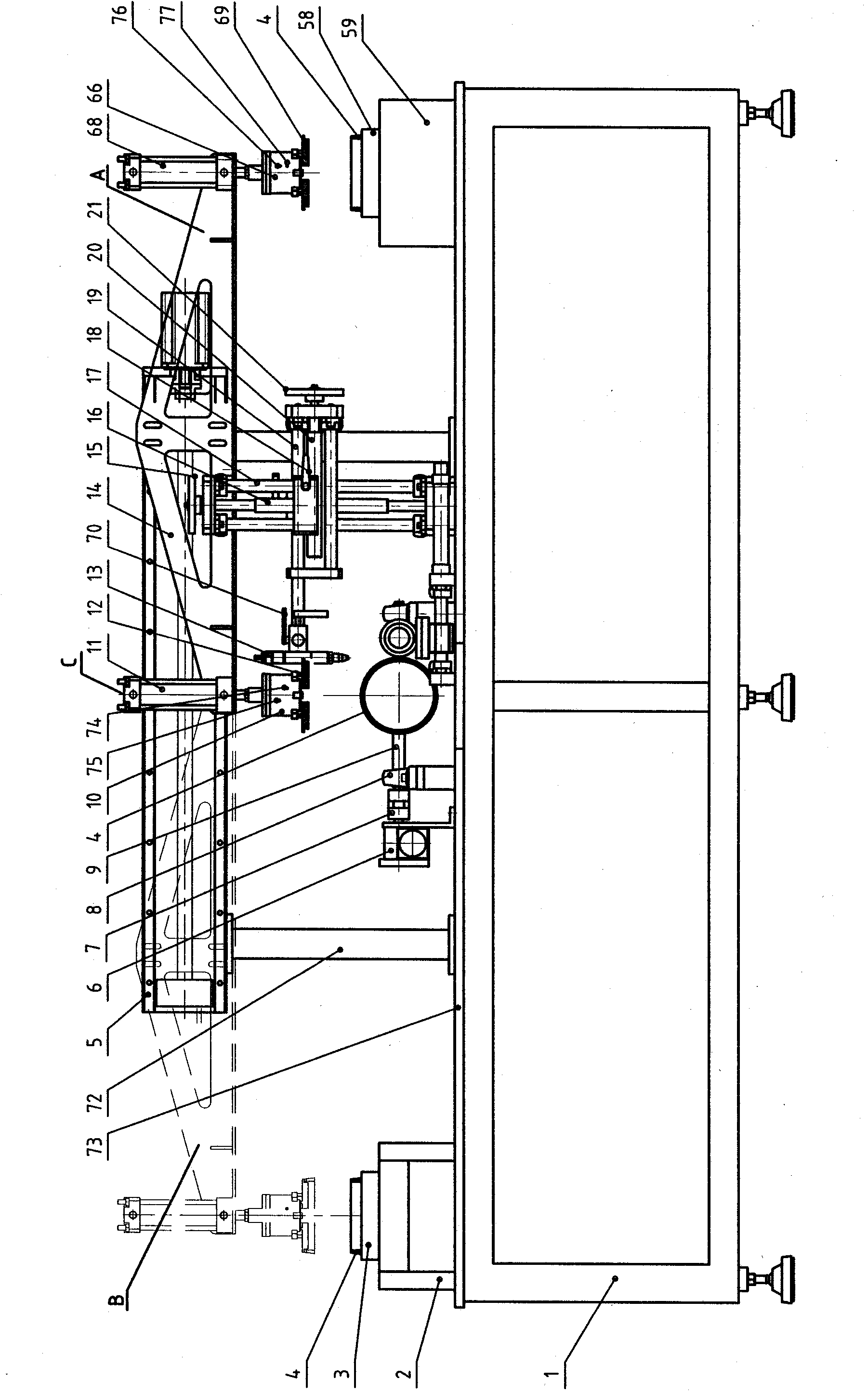
[0014] Specific implementation mode one: as figure 1 , figure 2 , image 3 , Figure 4 , Figure 5 and Figure 8 As shown, the fully automatic gluing equipment suitable for various parts described in this embodiment includes a feeding table 59, a transfer table 2, a parts lateral transfer device 5, a tensioning chuck A10, a tensioning chuck C10, a rotating The chuck device 23, the swing device, the rubber head adjusting device, the rubber scraping device, etc. are fixedly connected on the frame to form an integral body, the loading positioning mold 58 is fixed on the loading table panel 73, and the parts 4 are placed on the loading table manually. On the positioning mold 58, the function is to accurately position the parts 4, which is convenient for accurate and automatic handling of the parts 4. The conveyor belt 3 that can rotate continuously is installed on the conveyor table 2. Every time the parts are glued, it is a beat, and each time a beat is used, the chuck is te...

specific Embodiment approach 2

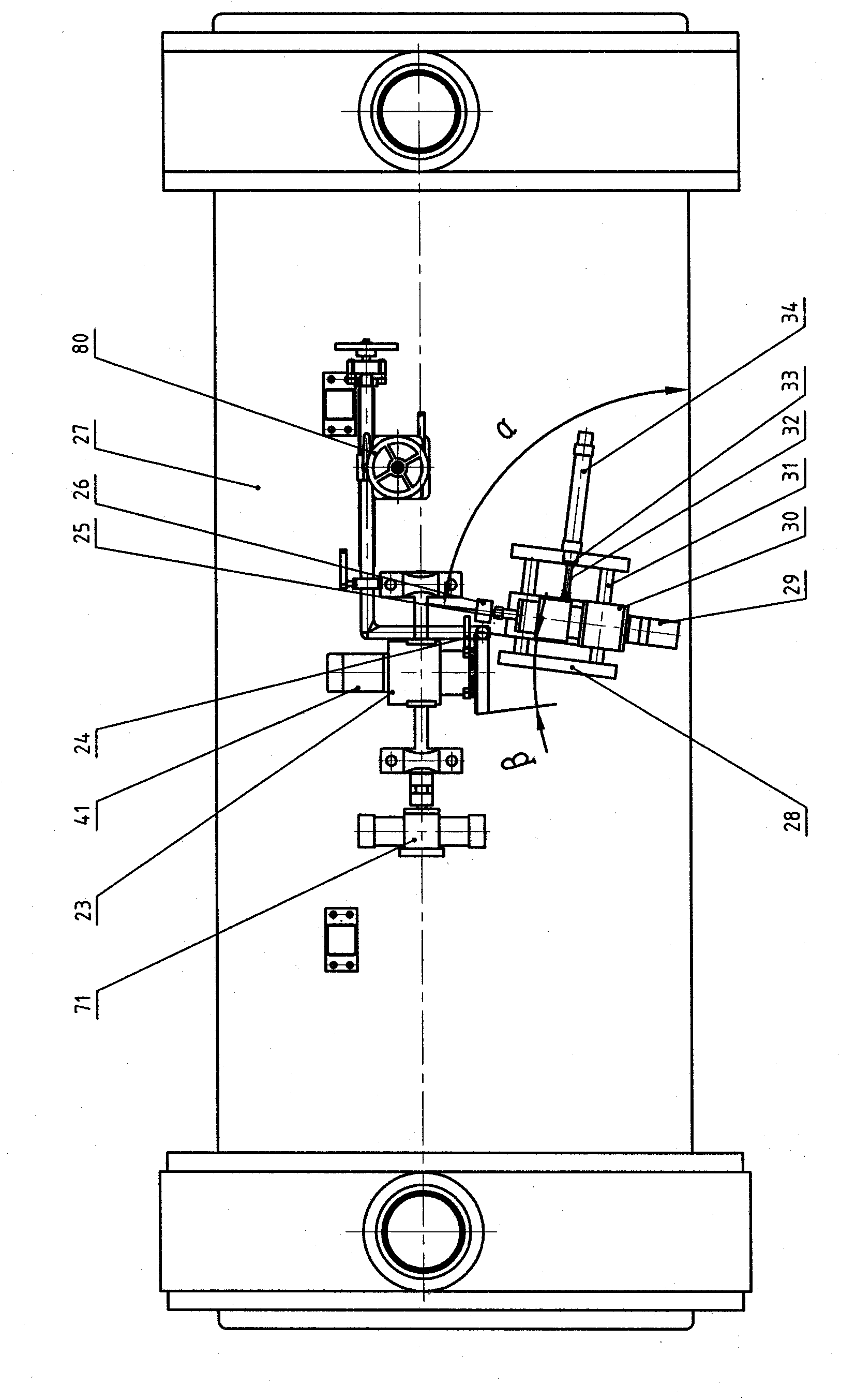
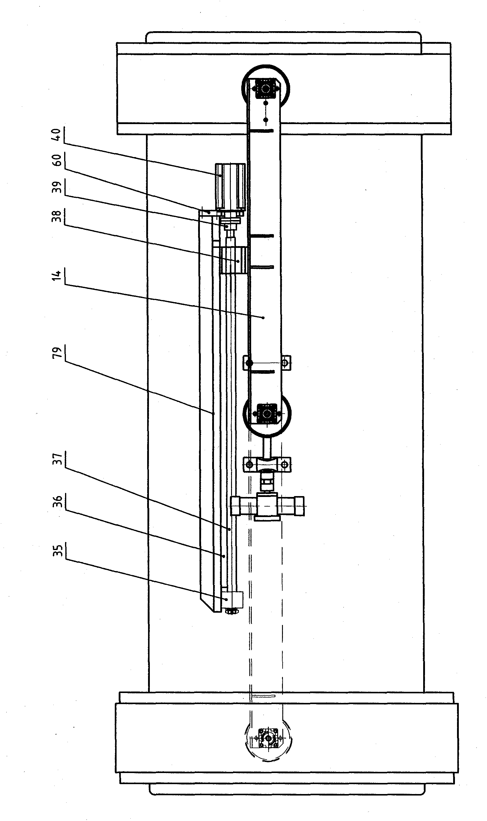
[0024] Specific implementation mode two: as Figure 6As shown, in this embodiment, the front view of the situation in which the feeding table 58 and the cylinder B68 are removed, the swing device 71, the rotating chuck device 23, the rubber head adjustment device 80, the rubber head adjustment device, and the rubber coating device 28 is exactly the same as the specific embodiment one, except that the loading workbench 58 and the cylinder B68 etc. are removed, the frame 1, the workbench panel 73, the parts transverse transfer device 5, and the mobile frame 14 are shortened, and the working position becomes C , B two, its principle of action is basically the same as the specific embodiment one. The conveying table 2, parts transverse conveying device 5, tensioning chuck A10, tensioning chuck C10, rotating chuck device 23, swinging device 71, rubber head adjusting device 80, rubber coating device 28, etc. described in this embodiment It is fixed and integrated on the frame, and ...

specific Embodiment approach 3

[0025] Specific implementation mode three: as figure 1 , Figure 6 As shown, in this embodiment, the conveyor belt 3 is stopped or removed, and the other action principles are basically the same as those in Embodiment 1 and Embodiment 2. It is just that after the parts transverse conveying device 5 transports the parts 4 from the C position to the B position, it is released onto the conveyor belt 3, and the parts 4 are manually removed.


PUM


Abstract

The invention provides fully-automatic gluing equipment suitable for various parts and relates to the fully-automatic gluing equipment. The fully-automatic gluing equipment solves the problem that the conventional cylindrical, ring-shaped, conical, circular truncated cone-shaped and circular truncated cone ring-shaped parts cannot be fully automatically glued on the same equipment. The fully-automatic gluing equipment comprises a machine frame, and a feeding workbench, a transmission platform, a part transverse transmission device, a tensioning collet A, a tensioning collet C, a rotary collet device, a swinging device, a glue head adjusting device and a glue scraping device which are fixed on the machine frame, wherein the feeding workbench comprises a feeding positioning die; the feeding positioning die is fixed on a feeding workbench panel; and the feeding positioning die is used for accurately positioning the parts and placing the parts in to the positioning die. The fully-automatic gluing equipment has high generality, can glue on the outer surfaces of the cylindrical, ring-shaped, conical, circular truncated cone-shaped and circular truncated cone ring-shaped parts and can glue on the inner surfaces of the cylindrical, ring-shaped, conical, circular truncated cone-shaped and circular truncated cone ring-shaped parts.

Description

technical field [0001] The invention relates to a fully automatic gluing equipment, which is suitable for gluing cylindrical, circular, conical, circular truncated and circular truncated ring parts. Background technique [0002] At present, there is no automatic equipment at home and abroad that can apply glue to cylindrical, circular, conical, circular and circular cone-shaped parts on one piece of equipment. The glue coating of the above-mentioned parts is almost always done with artificial brushes. There are very few methods such as spraying, roller brushing, and glue spraying, especially in the automobile industry and the home appliance industry. The glue is uneven, the stability is poor, and human factors affect the quality. Adhesives and solvents have a great impact on the health of operators. Existing equipment such as spraying, roller brushing, and gluing cannot realize automatic gluing, and it is easy to pollute other surfaces. It is highly specific and cannot be s...

Claims


Application Information

Patent Timeline
Patent Type & Authority Applications(China)
IPC IPC(8): B05C1/08B05C13/02B05C11/02
Inventor 韩毅军
Owner DALIAN HUAGONG INNOVATION TECH
Why Eureka
Try Eureka