Al technical title is built by PatSnap Al team. It summarizes the technical point description of the patent document.
A technology of gluing and carding, which is applied in the direction of coating and liquid coating on the surface, etc., which can solve the problem of poor uniformity of glue
Pending Publication Date: 2018-06-15
BEAUTIFUL CARD TECH SUZHOU CO LTD
View PDF0 Cites 11 Cited by
Summary
Abstract
Description
Claims
Application Information
AI Technical Summary
This helps you quickly interpret patents by identifying the three key elements:
Problems solved by technology
Method used
Benefits of technology
Problems solved by technology
At present, the card body is made by bonding multiple raw material boards. In the actual production of gluing, it is necessary to place the raw material boards in the mold with positioning grooves first, and then use the rubber cylinder for glue brushing. After the glue brushing is completed, The cylinder inside the mold is enough to push out the raw material plate. Since the glue attached to the surface of the rubber cylinder is poor in uniformity, the uniformity of the glue coated on the raw material plate is also poor.
Method used
Image
Click on the blue label to locate the original text in one second.
Reading with bidirectional positioning of images and text.
Examples
Embodiment Construction
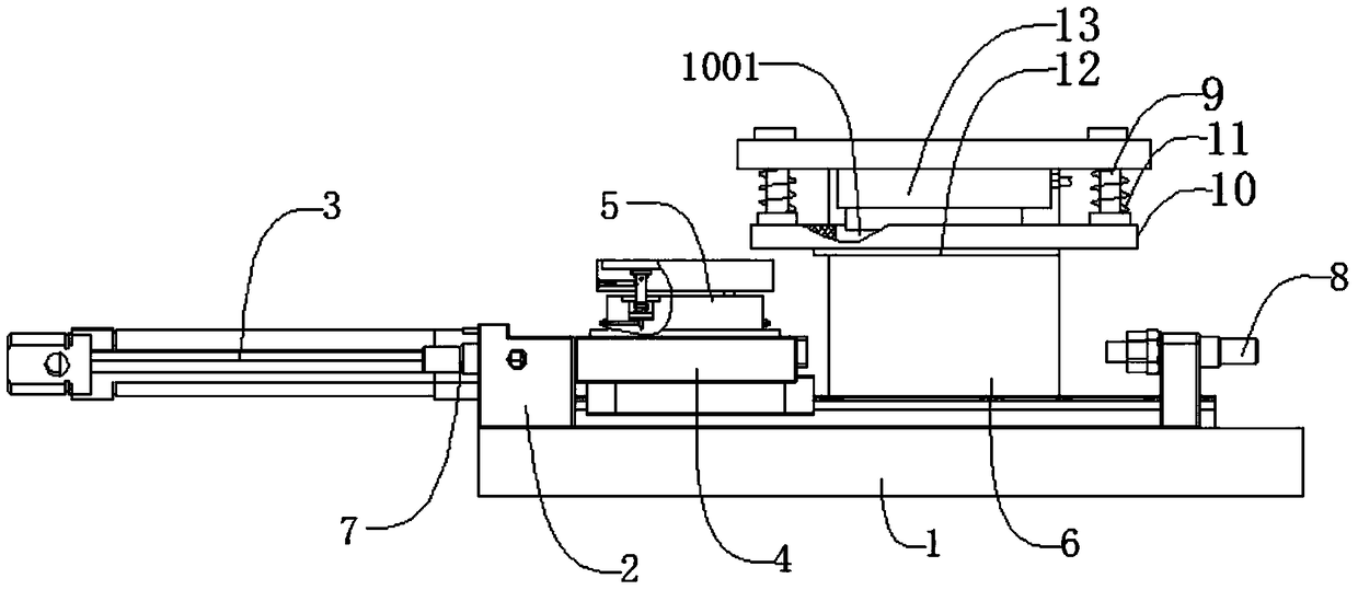
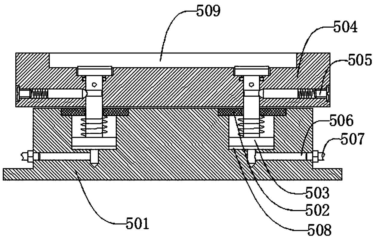
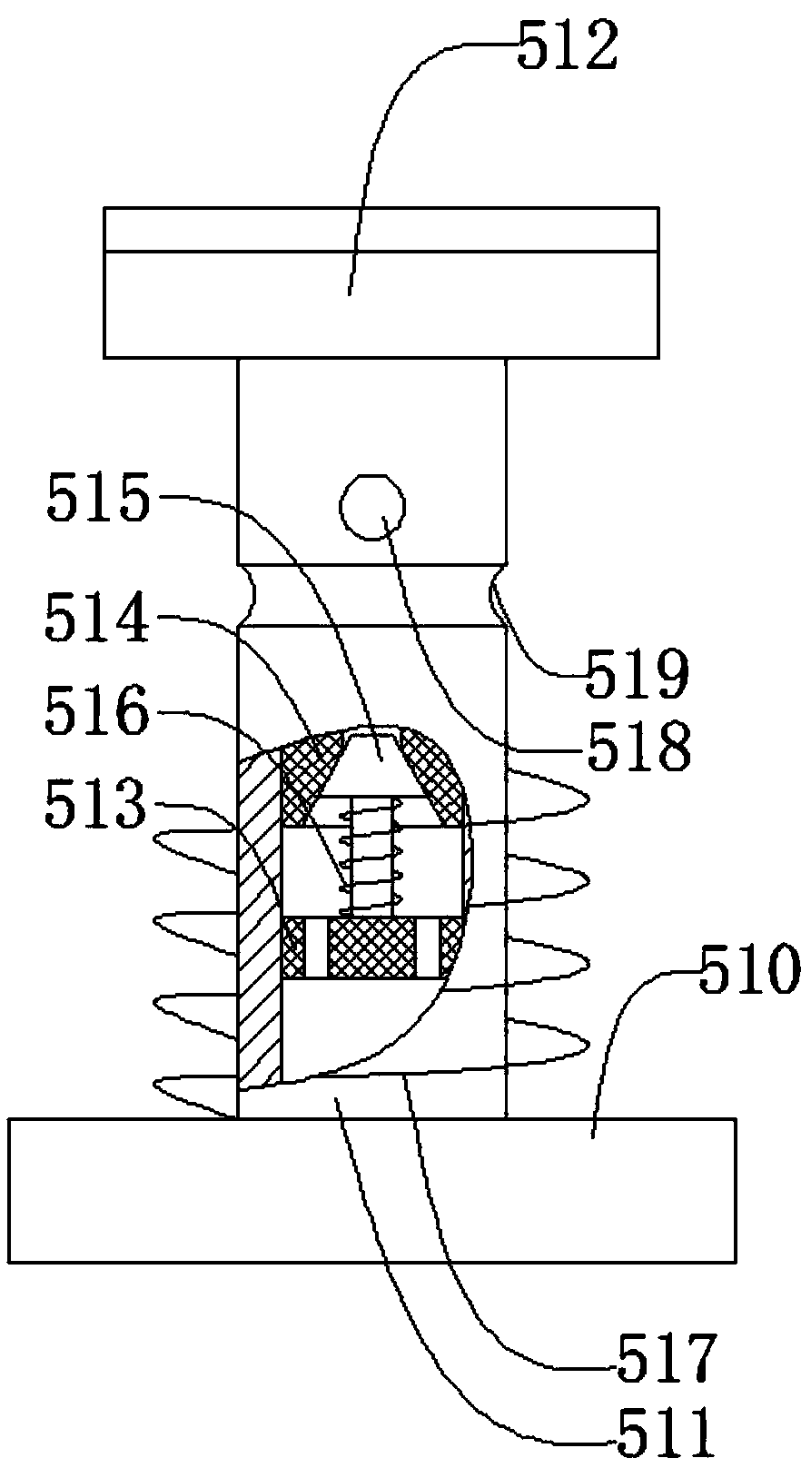
[0026] Such as figure 1 , figure 2 , image 3 , Figure 4 , Figure 5 , Image 6 , Figure 7 , Figure 8As shown, a card gluing mechanism includes a base 1, a fixed seat 2, a push cylinder 3, a sliding seat 4, a lifting and placing mechanism 5, a bracket 6, a first proximity switch 7, a second proximity switch 8, a guide Rod 9, pressure frame 10, first spring 11, glue equalizing plate 12 with several glue equalizing holes 1201, glue spreading mechanism 13, said fixing seat 2 is located on the left side of the upper end of base 1, said fixing seat 2 and The base 1 is connected by bolts, the pushing cylinder 3 is located on the left side of the fixed seat 2, the pushing cylinder 3 is connected with the fixed seat 2 by bolts, and the sliding seat 4 is located on the right side of the pushing cylinder 3 and is located The upper end of the base 1, the sliding seat 4 is connected with the pushing cylinder 3 by bolts, the sliding seat 4 can slide left and right along the base...
PUM
Abstract
The invention discloses a card gluing mechanism. The gluing mechanism comprises a base, a fixing base, a pushing air cylinder, a sliding base, a jacking and placing mechanism, a supporting frame, a first proximity switch, a second proximity switch, guide rods, a pressing frame, first springs, a glue uniformizing plate with a plurality of glue uniformizing holes and a gluing mechanism; and a raw material plate to be glued is placed in the jacking and placing mechanism, the pushing air cylinder pushes the sliding base to move rightwards in place, the jacking and placing mechanism drives the rawmaterial plate to move upwards to be in contact with the glue uniformizing plate, the first springs are compressed, the gluing mechanism penetrates through the pressing frame to be in contact with theglue uniformizing plate, then a glue solution coats the raw material plate due to the action of the surface tension, so that glue solution coating is completed. According to the card gluing mechanism, the structure is simple, gluing can be automatically carried out on the raw material plate, the jacking and placing mechanism can be used for carrying out positioning and fixing and exerting certainpressure on the raw material plate, so that gluing is uniform, the gluing process and the raw material plate ejection process are combined together, so that the action time is shortened, and the production efficiency is improved; and meanwhile, devices such as air cylinders do not need to be arranged, so that the production cost is effectively reduced.
Description
technical field [0001] The invention relates to a mechanical device, in particular to a card gluing mechanism. Background technique [0002] The existing electronic chip card is composed of a card body and a chip arranged on the card body, and a sensing coil connected with the chip to form a conduction is buried inside the card body, thereby forming an electronic chip card. At present, the card body is made by bonding multiple raw material boards. In the actual production of gluing, the raw material boards need to be placed in the mold with positioning grooves first, and then the glue is brushed with a rubber cylinder. After the glue is brushed, The cylinder inside the mold is enough to push out the raw material plate. Since the glue attached to the surface of the rubber cylinder is poor in uniformity, the uniformity of the glue coated on the raw material plate is also poor. In view of the above defects, it is necessary to design a card gluing mechanism. Contents of the i...
Claims
Application Information
Patent Timeline
Application Date:The date an application was filed.
Publication Date:The date a patent or application was officially published.
First Publication Date:The earliest publication date of a patent with the same application number.
Issue Date:Publication date of the patent grant document.
PCT Entry Date:The Entry date of PCT National Phase.
Estimated Expiry Date:The statutory expiry date of a patent right according to the Patent Law, and it is the longest term of protection that the patent right can achieve without the termination of the patent right due to other reasons(Term extension factor has been taken into account ).
Invalid Date:Actual expiry date is based on effective date or publication date of legal transaction data of invalid patent.