Interlock access control method

A control method and approach technology, applied in the field of interlocking approach control based on state transition diagrams, can solve problems such as system operation loopholes, project deadline extension, system loopholes, etc., to avoid potential safety hazards, simple implementation methods, and improved control. The effect of efficiency

Active Publication Date: 2012-07-11
TRAFFIC CONTROL TECH CO LTD
View PDF3 Cites 12 Cited by
  • Summary
  • Abstract
  • Description
  • Claims
  • Application Information

AI Technical Summary

Problems solved by technology

[0005] 1. In the process of designing and implementing interlocking route control, it is easy to ignore the route states that should exist, resulting in the situation that the output of some route states in the program does not correspond to the corresponding route state, which is likely to cause system safety hazards and system vulnerabilities
[0006] 2. It is difficult for designers and coders to fully grasp the state o

Method used


Image

  • Interlock access control method
  • Interlock access control method
  • Interlock access control method

Examples


Embodiment Construction

[0032] The interlocking route control method proposed by the present invention is described in detail as follows in conjunction with the accompanying drawings and embodiments.

[0033] The method of the invention utilizes the principle of the finite state machine to design the route control program. A finite state machine system refers to a system that exhibits different operating states at different stages, and these states are limited and non-overlapping. Such a system must at some point be in one of its states when it receives a subset of allowed inputs, generates a subset of possible responses, and transitions to a subset of possible states.

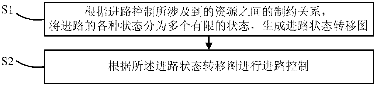
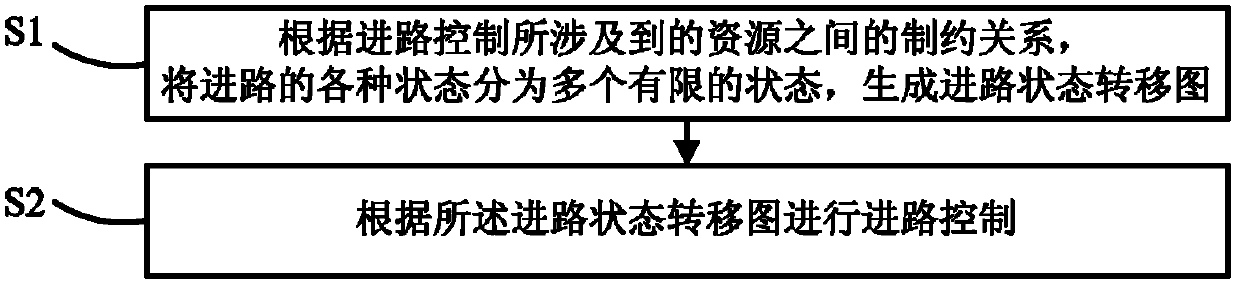
[0034] Such as figure 1 As shown, an interlocking approach control method according to an embodiment of the present invention includes steps:

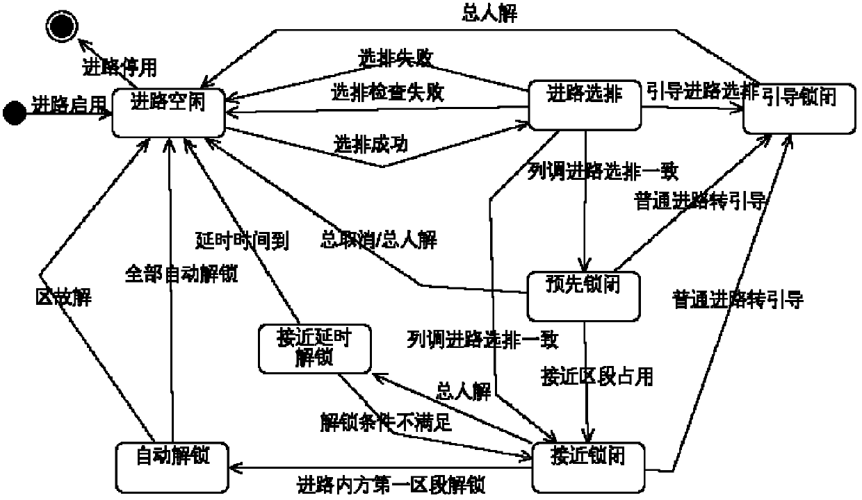
[0035] S1. According to the constraint relationship between the resources involved in the route control (including signals, switches, sections, routes and the status of trackside equipment,...


PUM


Abstract

The invention discloses an interlock access control method, which relates to the technical field of track traffic signal safety control and includes steps: S1 dividing various access states into a plurality of limited states and generating an access state transition diagram according to restrict relationship of resources related by access control; and S2 performing access control according to the access state transition diagram. The interlock access control method uses the access state transition diagram which is full in covering state as a reference, can well avoid possible safety hazard, simultaneously is easy in achieving method and improves control efficiency.

Description

technical field [0001] The invention relates to the technical field of rail transit signal safety control, in particular to an interlocking route control method based on a state transition diagram. Background technique [0002] A computer interlock system (Computer Interlock, CI) includes: an operation display machine, an interlock machine, and a controller of related equipment. Among them, the interlocking machine receives the command information transmitted by the upper display unit and the status information transmitted by the lower equipment controller, and performs interlocking inspection to ensure the safety of driving in the station. The interlocking machine is the core part of the interlocking system. The interlocking route control is the most important part of the interlocking machine. The route control performs a logical check on the status of the signal machine, turnout, section, route and trackside equipment , only after the logical checks are all passed and the...

Claims


Application Information

Patent Timeline
IPC IPC(8): B61L19/00B61L21/00
Inventor 许永成郭文章陈曦东王悉刘伟
Owner TRAFFIC CONTROL TECH CO LTD
Why Eureka
Try Eureka