Sputtering device

A technology for sputtering and workpieces to be plated, applied in sputtering plating, ion implantation plating, vacuum evaporation plating, etc., can solve problems such as low coating efficiency and limited number of workpieces, improve coating efficiency and improve space utilization rate effect

Inactive Publication Date: 2012-07-11
HONG FU JIN PRECISION IND (SHENZHEN) CO LTD +1
View PDF3 Cites 7 Cited by
  • Summary
  • Abstract
  • Description
  • Claims
  • Application Information

AI Technical Summary

Problems solved by technology

However, since the number of rods that can be arranged on the circumference is small, the number of workpieces to be plated that can be fixed is also small, so the number of workpieces that can be sputtered in one coating is limited, and the coating efficiency is low.

Method used


Image

  • Sputtering device
  • Sputtering device
  • Sputtering device

Examples


Embodiment Construction

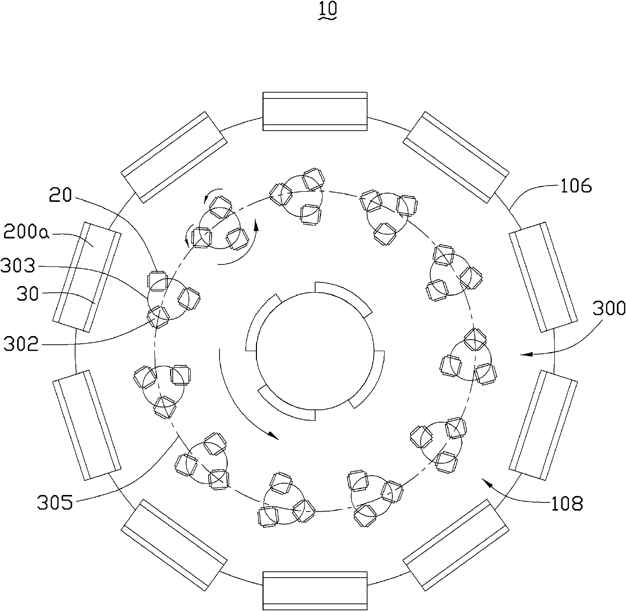
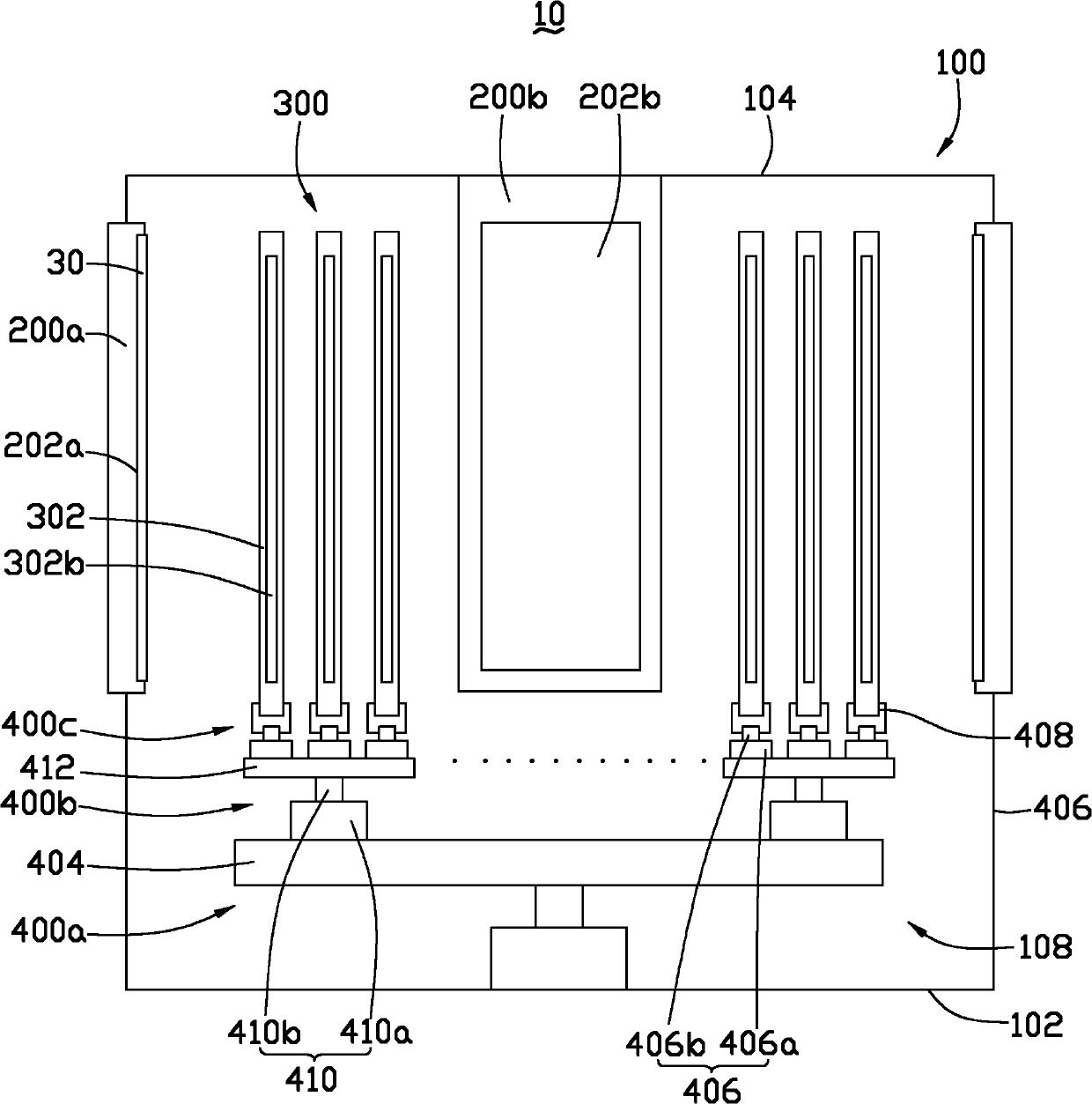
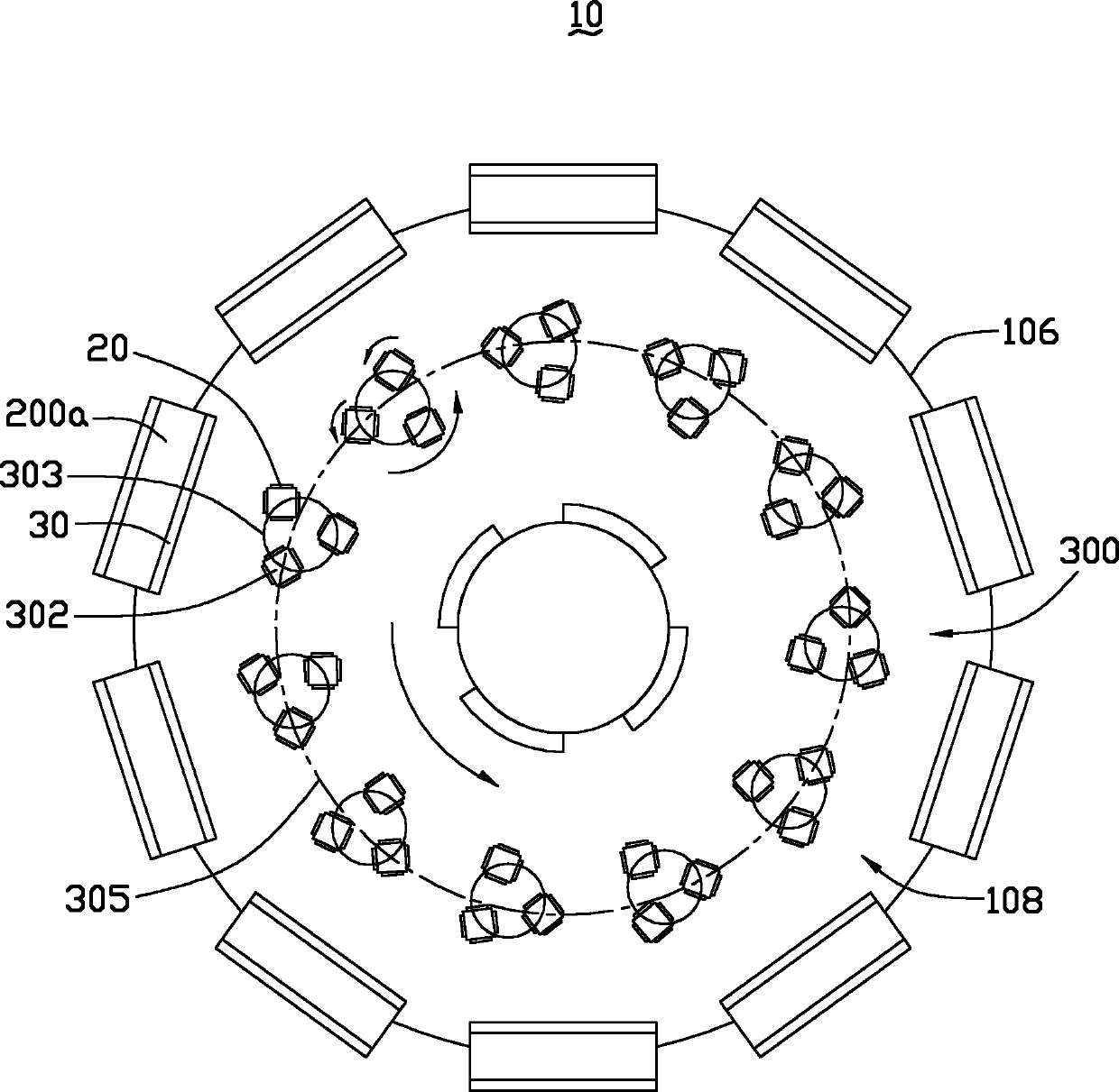
[0041] Please refer to figure 1 and figure 2 , The sputtering device 10 of the preferred embodiment of the present invention includes a housing 100, a plurality of first target holders 200a, a second target holder 200b, a plurality of rod groups 300, a first driver 400a, and a plurality of second driver 400b, and a plurality of third driver groups 400c.

[0042] The housing 100 defines a cavity 108 . Specifically, the housing 100 includes a bottom plate 102 , a top plate 104 and a side wall 106 . The bottom board 102 is opposite to the top board 104 . The side wall 106 connects the bottom board 102 and the top board 104 . Bottom plate 102 generally faces downward. The bottom plate 102 , the top plate 104 and the side walls 106 define a cavity 108 . The cavity 108 is cylindrical and used to define a space for sputtering coating.

[0043] A plurality of rod groups 300 are accommodated in the cavity 108 , arranged in parallel and arranged to form a second circle 305 . Ea...


PUM


Abstract

The invention provides a sputtering device, which comprises a casing, a plurality of material rod groups for fixing workpieces to be coated, a plurality of first target seats and second target seats for fixing targets, a first driver and a plurality of third driver groups. A cavity is defined by the casing, the plurality of material rod groups are accommodated in the cavity and parallelly arranged to form a second circle, and each material rod group comprises a plurality of material rods which are parallelly arranged to form a first circle. The plurality of the first target seats and the second target seats are arranged in the cavity and respectively arranged inside and outside of the second circle. Each of the third driver groups is connected to a corresponding material rod group so as to drive each material rod in the material rod group to rotate around the central axis of each material rod. The first driver is connected to the plurality of the third driver groups so as to drive the plurality of the material rod groups to rotate around the central axis of the second circle. More material rods can be arranged in the cavity so as to improve coating efficiency.

Description

technical field [0001] The invention relates to a sputtering device. Background technique [0002] A sputtering device generally includes a shell defining a coating cavity, a plurality of rods for fixing workpieces to be plated, and a plurality of target seats for fixing targets. The plurality of rods are generally arranged in parallel and distributed in a circle. The plurality of target bases are usually evenly spaced on the periphery of the cavity and surround the plurality of material rods. During the coating process, the workpiece to be coated is fixed on the rod and faces the target to receive the particles sputtered by the target, so as to be coated with the required film layer. However, since the number of rods that can be arranged on the one circumference is small, the number of workpieces to be plated that can be fixed is also small, so the number of workpieces that can be sputtered in one coating is limited, and the coating efficiency is low. Contents of the in...

Claims


Application Information

Patent Timeline
Patent Type & Authority Applications(China)
IPC IPC(8): C23C14/34C23C14/50
Inventor 吴佳颖
Owner HONG FU JIN PRECISION IND (SHENZHEN) CO LTD
Why Eureka
Try Eureka