
Hydraulic pipe protection structure of construction machinery

A technology for construction machinery and protection structures, which is applied in the direction of earthmoving machines/shovels, construction, etc., can solve the problems of increased operation procedures, increased costs, and large number of components, and achieves low cost, reduced number of components, and beneficial effects. effect on practicality

Active Publication Date: 2015-08-19
NIHON KENKI CO LTD
View PDF5 Cites 0 Cited by
  • Summary
  • Abstract
  • Description
  • Claims
  • Application Information

AI Technical Summary

Problems solved by technology

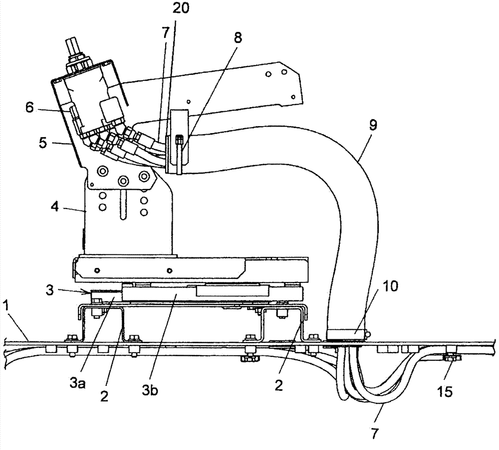
However, in this prior art, when the tube holder is mounted on the insertion hole portion of the vehicle surface and the control tube is held by the installed tube holder, it is necessary to fit the tube holder holding the control tube into the vehicle surface. The work on the rotating body, the work of supporting the rotating body shaft on the fixed bracket, and the work of fixing the fixed bracket to the vehicle surface with mounting screws make it easy to increase the number of work steps
In addition, this prior art requires a divided fixing bracket, mounting fastening screw, rotating body, and pipe holding portion, so the number of parts increases.
Because of this, there is a problem in the prior art that such a tube holder is installed in the insertion hole portion of the vehicle surface, and the work required to hold the control tube by the installed tube holder is increased.

Method used


Image

  • Hydraulic pipe protection structure of construction machinery
  • Hydraulic pipe protection structure of construction machinery
  • Hydraulic pipe protection structure of construction machinery

Examples


Embodiment Construction

[0035] Next, an embodiment of a hydraulic pipe protection structure for a construction machine according to the present invention will be described with reference to the drawings.

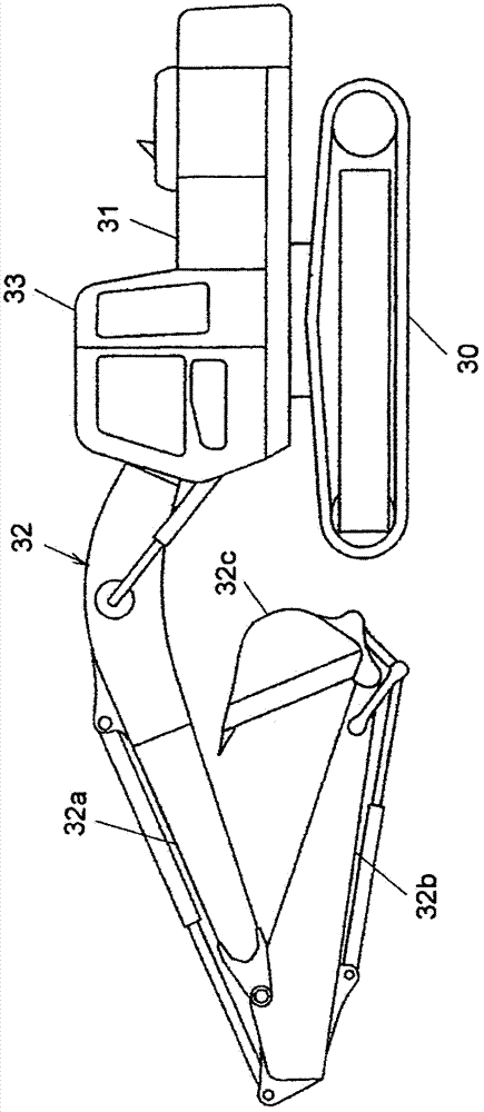
[0036] figure 1 It is a side view showing a hydraulic excavator cited as an example of a construction machine provided with the hydraulic pipe protection structure of the present invention.

[0037] as it should figure 1 As shown, the hydraulic excavator equipped with the hydraulic pipe protection structure of this embodiment includes a traveling body 30, a rotating body 31 arranged on the traveling body 30, and a working unit mounted on the rotating body 31 so as to be rotatable in the vertical direction. Device 32. The work implement 32 includes, for example, a beam 32a attached to the revolving body 31, an arm 32b attached to the tip of the beam 32a, and a bucket 32c attached to the tip of the arm 32b. A cab 33 is provided on the revolving body 31 , and the hydraulic pipe protection structure...


PUM


Abstract

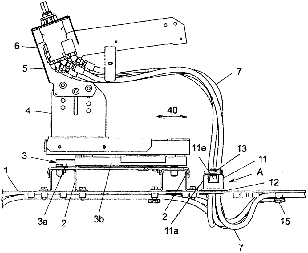
The invention provides a hydraulic pipe protection structure of an engineering machine, which can simply install a pipe retainer on an insertion hole part of a bottom plate, retain the operation of a hydraulic pipe by the installed pipe retainer and additionally reduce the number of the parts. A sleeve (11) for retaining the hydraulic pipe (7) is installed in the insertion hole (1a) of the bottom plate (1) and integrally composed of an upper cylinder wall (11a), a plurality of clamping slices (11e), a flange part (11b), a lower cylinder wall (11e) and a plurality of claw parts (11f). The hydraulic pipe (7) inserted into an insertion space (11d) of the sleeve (11) is connected with a belt (13) clamped on a projection part (11e1) of the clamping slice (11e). In addition, the sleeve (11) is embedded into the insertion hole (1a) of the bottom plate (1) by the claw parts (11f).

Description

technical field [0001] The present invention relates to a hydraulic pipe protection structure for a construction machine, which is mounted on a construction machine such as a hydraulic excavator, and includes a pipe holding portion arranged in an insertion hole portion of a bottom plate of a cab and holding a hydraulic pipe passing through the insertion hole. Background technique [0002] As such a conventional technique, there is a technique disclosed in Patent Document 1. This prior art is configured to fix the divided fixing bracket to the vehicle surface, that is, the insertion hole portion formed on the ground of the cab of the construction machine, that is, the floor plate, by using fastening screws, so that the rotating body can rotate freely. The ground shaft is supported by the fixed bracket, and a tube holding portion that holds a control tube passing through the insertion hole, that is, a hydraulic tube, is fitted in the rotating body. With such a configuration, ...

Claims


Application Information

Patent Timeline
Patent Type & Authority Patents(China)
IPC IPC(8): E02F9/16
CPCE02F9/14E02F9/22E02F9/2271E02F9/2275E02F9/24
Inventor 渡边史泰
Owner NIHON KENKI CO LTD
Learn More